tag 标签: timer

相关博文
  • 热度 27
    2020-6-6 19:46
    2133 次阅读|
    0 个评论
    【MM32 eMiniBoard】01.开箱:板载部分硬件测试
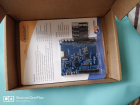
    【 MM32 eMiniBoard 】 01. 开箱:板载部分硬件测试 写在前面的话 这一年因为工作需要,开始接触无线通信方面的工作,越来越多的了解和接触到关于无线通信的知识点,也为各种数据通信方式而苦恼。这次无意看到面包板上的 MM32W3 开发板评测活动,被其内置蓝牙模块所吸引,随后申请并有幸被选中为体验者之一,非常激动。 开箱 开箱入眼就是这样一个小板子安静的躺在包装盒内: 拿出板子和卡片,背面如下,我估计这类开发板现在都是这样设计的包装了,正面板子芯片资源介绍,背面产品推广广告。 板子真容如下,背面就不往上放了,相机效果太差。 下面这个按键设计是我比较喜欢的地方,侧边放置,侧面按压,虽然实际使用效果一般,但是这个设计还是很 NICE。 开发板简介(手册搬运) MM32 eMiniBoard 蓝牙开发板,这个板子的名字基本上包含了芯片的一切特点,内核、特色资源(蓝牙)。 MM32 eMiniBoard 蓝牙开 发板具有如下特点: 支持 MindMotion MM32 Cortex-M 系列 MCU 开发评估 支持 Keil uVision v5.0 / IAR EWARM v7.80 以上的集成开发环境 支持 MindMotion MM32 FDS 固件开发平台 支持 MindMotion MM32 Program 编程软件 开发板 MCU 供电电源基于 3.3V 电压设计 支持高达 4KV EFT 抗干扰能力 Insight 系列 MM32 eMiniBoard 开发板用户手册 v0.90 内嵌 MM32-LINK-OB 在线仿真器,支持 SWD 调试接口以及智能连接的 CDC 虚拟串口 仿真器 USB 接口或目标 MCU USB 接口供电 4- 侧贴按键 4-LED 1-UART 连接器 1 无源扬声器 1-USB 连接器 1-16Mbit 的 SPI Flash 存储器 1-2048bit 的 I2C 存储器 1 模拟输入电位器 1 个内置扩展功能和 MCU 引脚功能选择开关与 MCU 管脚相同 ( 部分功能引脚未引出 ) 的 0.1 英寸间距的双排直针插座 芯片简介(手册搬运) MM32W3 系列是超低功耗的单模蓝牙芯片,射频采用 2.4GHz ISM 频段的频率, 2MHz 信道间隔,符合蓝牙规范。 MM32W373PSB 使用高性能的 ARM® Cortex®-M3 为内核的 32 位微控制器,最高工作频率可达 96MHz ,内置高速存储器,丰富的增强型 I/O 端口和外设连接到两条 APB 总线。 灵动微 MM32W373PSB 包含 2 个 12 位 ADC 、 2 个 12 位的 DAC 、 3 个 16 位通用定时器和 1 个 PWM 高级定时器,还包含标准的通信接口: 3 个 UART 接口、 2 个 I2C 接口、 1 个 SPI 接口和 1 个 USB 接口。 MM32W3 产品系列工作电压为 2.3V ~ 3.9V ,工作温度范围包含 -40 ℃ ~ +85 ℃常规型。多种省电工作模式保证低功耗应用的要求。 外设1:LED+KEY 进入正题,板载外设KEY+LED,这部分具体可参考上图KEY特写部分,原理图如下 LED的原理图还好,KEY的图就有点惨不忍睹了,连线混乱,看的我眼花缭乱,半天愣是没看出他的接线方式,上下拉方式我都分不清楚,确实不应该。 调试这个几个KEY真的浪费了点时间,但是还好,经过不懈学习总算搞懂它们了。 部分驱动程序如下: GPIO_InitStructure.GPIO_Pin = KEY1_GPIO_PIN; // 设置按键的引脚为浮空输入 GPIO_InitStructure.GPIO_Mode =GPIO_Mode_IPD; //选择按键的引脚 GPIO_InitStructure.GPIO_Pin = KEY2_GPIO_PIN ; //设置按键的引脚为浮空输入 GPIO_InitStructure.GPIO_Mode = GPIO_Mode_IPU; //选择按键的引脚 GPIO_InitStructure.GPIO_Pin = KEY3_GPIO_PIN ; //设置按键的引脚为浮空输入 GPIO_InitStructure.GPIO_Mode = GPIO_Mode_IPU; //选择按键的引脚 GPIO_InitStructure.GPIO_Pin = KEY4_GPIO_PIN ; //设置按键的引脚为浮空输入 GPIO_InitStructure.GPIO_Mode = GPIO_Mode_IPU; /* * 函数名:Key1_Scan * 描述 :检测是否有按键按下 * 输入 :GPIOx:x 可以是 A,B,C,D或者 E * GPIO_Pin:待读取的端口位 * 输出 :KEY_OFF(没按下按键)、KEY_ON(按下按键) */ uint8_t Key1_Scan(GPIO_TypeDef* GPIOx,uint16_t GPIO_Pin) { /*检测是否有按键按下 */ if(GPIO_ReadInputDataBit(GPIOx,GPIO_Pin) == KEY1_ON ) { /*等待按键释放 */ while(GPIO_ReadInputDataBit(GPIOx,GPIO_Pin) == KEY1_ON); return KEY1_ON; } else return KEY1_OFF; } /* * 函数名:Key_Scan * 描述 :检测是否有按键按下(Key2,Key3,Key4) * 输入 :GPIOx:x 可以是 A,B,C,D或者 E * GPIO_Pin:待读取的端口位 * 输出 :KEY_OFF(没按下按键)、KEY_ON(按下按键) */ uint8_t Key_Scan(GPIO_TypeDef* GPIOx,uint16_t GPIO_Pin) { /*检测是否有按键按下 */ if(GPIO_ReadInputDataBit(GPIOx,GPIO_Pin) == KEY_ON ) { /*等待按键释放 */ while(GPIO_ReadInputDataBit(GPIOx,GPIO_Pin) == KEY_ON); return KEY_ON; } else return KEY_OFF; } 这里面自己宏定义的地方比较多,所以.h文件就不贴了,我把程序整理一下,工程直接发出来给大家参考。 这里要解释一下Buzzer这一部分,之所以加在这里是因为前面以为它是有源蜂鸣器,所以直接当LED驱动了。具体看后面蜂鸣器的驱动。 KEY这里主要看一下一脚设置模式和扫描函数就好,比较简单,就不多说了 GPIO_InitStructure.GPIO_Pin = KEY1_GPIO_PIN; // 设置按键的引脚为浮空输入 GPIO_InitStructure.GPIO_Mode =GPIO_Mode_IPD; //选择按键的引脚 GPIO_InitStructure.GPIO_Pin = KEY2_GPIO_PIN ; //设置按键的引脚为浮空输入 GPIO_InitStructure.GPIO_Mode = GPIO_Mode_IPU; //选择按键的引脚 GPIO_InitStructure.GPIO_Pin = KEY3_GPIO_PIN ; //设置按键的引脚为浮空输入 GPIO_InitStructure.GPIO_Mode = GPIO_Mode_IPU; //选择按键的引脚 GPIO_InitStructure.GPIO_Pin = KEY4_GPIO_PIN ; //设置按键的引脚为浮空输入 GPIO_InitStructure.GPIO_Mode = GPIO_Mode_IPU; /* * 函数名:Key1_Scan * 描述 :检测是否有按键按下 * 输入 :GPIOx:x 可以是 A,B,C,D或者 E * GPIO_Pin:待读取的端口位 * 输出 :KEY_OFF(没按下按键)、KEY_ON(按下按键) */ uint8_t Key1_Scan(GPIO_TypeDef* GPIOx,uint16_t GPIO_Pin) { /*检测是否有按键按下 */ if(GPIO_ReadInputDataBit(GPIOx,GPIO_Pin) == KEY1_ON ) { /*等待按键释放 */ while(GPIO_ReadInputDataBit(GPIOx,GPIO_Pin) == KEY1_ON); return KEY1_ON; } else return KEY1_OFF; } /* * 函数名:Key_Scan * 描述 :检测是否有按键按下(Key2,Key3,Key4) * 输入 :GPIOx:x 可以是 A,B,C,D或者 E * GPIO_Pin:待读取的端口位 * 输出 :KEY_OFF(没按下按键)、KEY_ON(按下按键) */ uint8_t Key_Scan(GPIO_TypeDef* GPIOx,uint16_t GPIO_Pin) { /*检测是否有按键按下 */ if(GPIO_ReadInputDataBit(GPIOx,GPIO_Pin) == KEY_ON ) { /*等待按键释放 */ while(GPIO_ReadInputDataBit(GPIOx,GPIO_Pin) == KEY_ON); return KEY_ON; } else return KEY_OFF; } 外设2:蜂鸣器 这次开箱测试,蜂鸣器当然必不可少。可是用高低电平驱动时,发现蜂鸣器竟然不会叫。随后仔细查看资料后发现,这个蜂鸣器是无源蜂鸣器,且硬件驱动方式也比较特殊。有个直 流隔离电 容。电路如图所示。 蜂鸣器是普通无源蜂鸣器,或者说就是类似于电脑的扬声器。单片机 I/O 口来的是一定频率的交流信号,也就是正半周高电位,负半周低电位(接地或者负电压),这样在正半周时有电流流过三极管 B-E 间,三极管导通,低电位时给电容放电,同时三极管截止。 二极管的作用是吸收蜂鸣器线圈的反响脉冲避免损坏三极管(和继电器上并联二极管道理一样)这样,就可以通过软件控制让单片机 I/O 口输出不同频率方波,蜂鸣器就能发出不同频率的声音。不仅仅局限于一般有源蜂鸣器的单调滴滴声,通过软件设计可以有不同频率的操作音,持续的报警音,甚至是一首“ 致爱丽丝 ”乐曲。 这两端话是我在网上看到的,直接复制粘贴过来了,感觉解释的很到位,和这块板子就是差个驱动MOS管,但其实是一样的。置于效果呢,我从网上找了两个音乐素材(欢乐颂、遇见),拍了个视频有点大,后面看看能不能上传上来,或者有兴趣也可以下载程序自己体验一下,还是挺好玩的。 这些程序就不贴了,我会把工程文件直接放上来。 外设3:EEPROM(I2C) I2C这里,没什么亮点,芯片硬件配置的我头大,最后还是用模拟的方式,一次成功。 电路什么的我就不放上来了,效果图如下: 到这里我的这个测试基本上就要结束了,因为板载外设资源HK25Q16C和ADC电压采集部分,我搞了两天,也没搞出个结果,所以后面再说; 然后再说一下,后面主要再围绕蓝牙模块做个评测,因为这个才是我最关心的东西,也是厂家的亮点,一定要有。 最后,工程文件上传一下。
  • 热度 19
    2014-7-6 22:41
    1264 次阅读|
    0 个评论
    在现有 http://www.myexception.cn/mobile/1436453.html 关于几个Timer的一个总结 Contiki源代码(Contiki版本3.X)中,在调用rtimer时,需要调用者获取当前的RITMER_NOW,然后在此基础上加上需要的time然后进行定时器调度。但是这样里边,如果存在多个定时任务的时候,如何处理呢?而且如果后一个定时任务的time正好小于前一个,又如何保证后一个被调用呢?在现有的rtimer中,没有看到这样的代码。由这份邮件列表的内容可以看到截止2013年11月16日,Contiki的Rtimer只支持1个Rtimer.   Message: 4 Date: Sat, 16 Nov 2013 17:35:16 +0100 (CET) From: Beno?t Th?baudeau benoit.thebaudeau@advansee.com Subject: Rtimer  limitations To: Contiki developer mailing list         contiki-developers@lists.sourceforge.net Message-ID:         1772566825.397867.1384619716871.JavaMail.zimbra@advansee.com Content-Type: text/plain; charset=utf-8 Hi all, Rtimers are very useful in order to schedule hard real-time tasks, while Ctimers may be delayed. However, looking at their implementation in core/sys/ rtimer .{ c |h}, it seems that only a single  Rtimer  instance is supported at once. This is a big issue since it means that only a single  Rtimer  can be used in the firmware, or that  Rtimer  users have to know each other in order not to make Rtimers collide. Is it the expected behavior? Moreover, this limitation is not documented. Any comment? Best regards, Beno?t ------------------------------ Message: 5 Date: Sat, 16 Nov 2013 17:41:24 +0100 From: Adam Dunkels adam@thingsquare.com Subject: Re: Rtimer  limitations To: Contiki developer mailing list         contiki-developers@lists.sourceforge.net Message-ID:         CAEW- RJ5WHcsMjoTPXSFNMLhmyboJXV6L63 ctJ5xkCgJ66j= GHw@mail.gmail.com Content-Type: text/plain; charset="iso-8859-1" The  rtimer  API is supposed to support multiple rtimers but, yeah, the implementation only supports one. Until we've got stable code for multiple rtimers, this is what we have. /adam On Sat, Nov 16, 2013 at 5:35 PM, Beno?t Th?baudeau benoit.thebaudeau@advansee.com wrote:
  • 热度 15
    2014-3-31 17:40
    1534 次阅读|
    1 个评论
    I have memories of listening to the original radio version of Douglas Adams' The Hitchhiker's Guide to the Galaxy . This was back in the late 1970s when I was still a bright-eyed, bushy-tailed student at university (before life ground me down into the sad, bitter, twisted man you see before you today). There were some great lines in that program, such as when the alien, Ford Prefect, tells our hero, Arthur Dent: "Time is an illusion. Lunchtime doubly so." Arthur immediately responds "Very deep. You should send that in to the Reader's Digest . They've got a page for people like you." Like so many of these sayings, Adams managed to link two disparate ideas together—one important and one trivial—for humourous effect. In this case, on the one hand we have the fact that the true nature of time is an incredibly deep question that is not well understood. On the other hand we have the fact that time seems to go faster when you are doing something you enjoy, like having lunch. But we digress... The reason I'm waffling on about this here is that my chum Jay Dowling just pointed me at a rather fascinating website called Poodwaddle.com .   Much like the time-traveling inventor in H.G. Wells's The Time Machine , the folks at Poodwaddle are dedicated to time, as in the past, the present, and the future. In addition to a bunch of other stuff, they gather statistics about the past and present predictions for the future. When you visit the Poodwaddle website, you can see all of these statistics being displayed in real-time. These range from the number of people being born and passing away, to the amount of energy being consumed, to the number of people who have just had their first kiss, to the amount of beer being produced. (Oooh, beer!) Some of this stuff is scary, like the Oil Reserve Depletion Timer, which predicts that the world will run out of oil in approximately 47 years based on current rates of production. Other information is strangely fascinating, like watching the real-time numbers of births and deaths and the corresponding change in the world's population. For example, according to Poodwaddle, 8,648 people have been born and 3,639 people have died since I started writing this column, which means the overall population has increased by around 5,000 souls. All I can say is that it makes you think. Speaking of which, what do you think?  
  • 热度 22
    2012-5-23 09:08
    1170 次阅读|
    0 个评论
    简介 这篇文档主要介绍了在W7100A中使用UART通信的基本示例程序。所有的这些示例代码都是基于C语言和Keil编译器完成的。详情请参考W7100A数据手册‘第6章UART’中关于 UART、寄存器、中断等等。 图表1为设置UART波特率所用到的各个寄存器。定时器1(Timer1)相关的寄存器是SMOD和TH1,和定时器2(Timer2)相关的寄存器是RLDH和RLDL。 图表1.波特率设置例子   波特率(bps) 定时器 1(Timer1) / 模式 2 定时器 2(Timer2) TH1(0x8D) RLDH(0xCB), RLDL(0xCA) SMOD = ‘0’ SMOD = ‘1’ 2400 160(0xA0) 64(0x40) 64384(0XFB80) 4800 208(0xD0) 160(0xA0) 64960(0xFDC0) 9600 232(0xE8) 208(0xD0) 65248(0xFEE0) 14400 240(0xF0) 224(0xE0) 65344(0XFF40) 19200 244(0xF4) 232(0xE8) 65392(0XFF70) 28800 248(0xF8) 240(0xF0) 65440(0xFFA0) 38400 250(0xFA) 244(0xF4) 65464(0XFFB8) 57600 252(0xFC) 248(0xF8) 65488(0xFFD0) 115200 254(0xFE) 252(0xFC) 65512(0xFFE8) 230400 255(0xFF) 254(0xFE) 65524(0xFFF4) 在一些UART通信的示例中,UART通信有固定的波特率(模式0和模式2)。如果是这种波特率固定的情况,请参考W7100A数据手册第6章UART关于波特率的计算方法。所有的程序都是关于回送(Echo-back)的例子,送回由串行通信中接收到的信息。 W7100A中UART有4个模式,从UART模式0到UART模式3。每个模式下的示例代码的实现将在后面详细介绍。 模式0, 8位UART, 固定波特率 void Init_iMCU(void) { SCON = 0x10;        // 串行模式0, SM00 = 0, SM01 =0, REN=1 }   void PutByte(unsigned char byData) {        SBUF = byData;     //向串行缓存器中写入数据        while(!TI);         //等待直到所有的数据记录完成        TI = 0;             //清除发送中断 }   unsigned char GetByte(void)    {        unsigned char byData;      // 等待直到数据接收完成        while(!RI);        RI = 0;                  //清除RI        byData = SBUF;            //读取数据        return byData; }   void main() {       Init_iMCU();                      //调用Init_iMCU()函数       while(1)  PutByte(GetByte());     //回送(Echo-back)接收到的数据 } 关于UART模式0下的波特率,选择内部时钟12分频(f osc /12)。考虑到W7100A的内部时钟创建了一个非常快的波特率时钟,频率大小为7.3MHz。这种固定波特率、高速的波特率时钟情况下,通常情况下不会选择模式0。这是因为模式0用的是同步传输,没有起始位和停止位。 在所有的这些示例代码中,在Init_iMCU()函数中将SCON寄存器设置为0x10。PutByte()函数可以把串行输入写入串行缓存器 中,然后等待直到所有的数据发送完成,最后清除TI。GetByte()函数则可以返回接收到的串行数据,并且等待直到所有的数据接收完成,最后清除 RI。Main()函数中,则是通过调用所有的Init_iMCU()、PutByte()、GetByte()函数将所有接收到的数据进行输出。 模式1, 8位UART, 可变波特率 因为模式1使用异步通信,起始位和停止位分别位于数据的开头和结尾。定时器1(Timer1)和定时器2(Timer2)溢出产生波特率。后面将详细介绍各个模式下的示例代码程序。   定时器1(Timer1) 时钟源 void Init_iMCU(void) { SCON = 0x50;      // 串行模式1, SM00 = 0, SM01 =1, REN=1 TMOD |= 0x20;          // 定时器1(Timer1)模式2 PCON |= 0x80;          // SMOD0 = 1 TL1 = 0xFC;            // 波特率设定为115200bps TH1 = 0xFC;            // 参考W7100A数据手册 TR1 = 1;                //启动定时器1(Timer1) }   void PutByte(unsigned char byData) {        SBUF = byData;     // 向串行缓存器中写入数据        while(!TI);         // 等待数据记录完成        TI = 0;             // 清除传输中断 }   unsigned char GetByte(void) {        unsigned char byData;      //等待直到数据接收        while(!RI);        RI = 0;                  //清除RI        byData = SBUF;                  // 读取数据        return byData; }   void main() {       Init_iMCU();                      //调用Init_iMCU函数       while(1)  PutByte(GetByte());     //回送(Echo-back)接收到的数据 }   在UART模式1下可以交换使用定时器1(Timer1)和定时器2(Timer2)来设定波特率。在这一章,我们使用定时器1(Timer1)来设定波特率的值。详细请参考W7100A数据手册查看关于波特率的设置。 示例程序中,将SCON寄存器的值设定为0x50,同时设定Timer1在模式2。如果要设置波特率的值,还要将SMOD位置1,TH1寄存器的值设定为0xFC。此时,波特率的值为 115200bps。其它用来输出的代码程序也如同第2章的接收程序大致相同。 定时器2(Timer2) 时钟源 void Init_iMCU(void) { SCON = 0x50;        // 串行模式1, SM00 = 0, SM01 =1, REN=1 T2CON = 0x30;          // 定时器2(Timer2)波特率发生器模式 TH2 = 0xFF;            // 波特率设置为115200bps TL2 = 0xE8;             // 请参考W7100A数据手册  RLDH = 0xFF;           // 重新重载波特率为115200bps RLDL = 0xE8;            // 重新重载波特率为115200bps TR2 = 1;                // 启动定时器2(Timer2) }   void PutByte(unsigned char byData) {        SBUF = byData;     // 向串行缓存器中写入数据        while(!TI);         // 等待直到所有的数据记录完成        TI = 0;             // 清除传输中断 }   unsigned char GetByte(void)    {        unsigned char byData;      // 等待数据接收        while(!RI);        RI = 0;                  //清除RI        byData = SBUF;           // 读取数据        return byData; }   void main() {       Init_iMCU();                      //调用Init_iMCU函数       while(1)  PutByte(GetByte());     //回送(Echo-back)接收到的数据 } UART在模式1下可以交换使用定时器1(Timer1)和定时器2(Timer2)来设定波特率的值。在这一章节,利用定时器2(Timer2)来设定波特率的值。详细请参考W7100A数据手册。 在示例代码中,将SCON寄存器设置为0x50,选择定时器2(Timer2)为波特率产生器模式。为了能够正确的设定波特率的值,还需要将TH2 和TL2分别设为0xFF和0xE8。这样设置完成后,波特率的值就是115200bps。RLDH和RLDL的值可以重新重载,分别定义为0xFF和 0xE8。其它用来输出的代码程序也如同第2章的接收程序大致相同。 未完待续~~ 明天我们还会继续给大家献上如何实现W7100A中的UART,敬请期待~~  
  • 热度 16
    2011-5-5 18:13
    1950 次阅读|
    0 个评论
    Some of you may be familiar with Marcel Proust's seven-volume work À la recherché du temps perdu (usually translated as Remembrances of Things Past or In Search of Lost Time ), either first-hand or through one of the many summary notes and guides available for it. (I'm in the latter category, I can assure you.) One important incident is when he receives a madeleine—a small, cake-like cookie—with his tea, and it brings back to him a flood of memories that runs nearly an entire volume of the work (you don't want M. Proust working in the cubicle next to yours, that's for sure!)   I had a similar "madeleine" experience recently. Back in the days "B.C." (before computers) era, when the earth was still flat, and when I was an innocent youth, I learned "electricity" by building basic electrical circuits—battery, wire, bell, electromagnet, knife switch, lamp, that type of stuff—all built on a wooden board (yes, folks, a genuine breadboard) using what were called Fahnestock clips for connection points. These clips were cheap, easy to screw to the board, easy to use, and easy to add/remove wires.   I haven't seen or heard of Fahnestock clips in many years, I didn't even know if you could get them. So imagine my surprise when I am paging through the latest catalog from Micro-Mark (a wonderful source of tools and fixtures for modelmaking), and there they were.   The ironic thing about them is that they were easy to use, but not very reliable, especially if the wire you inserted had a slight kink, or you had two or three wires in the clip, or there was any movement of the wires. I do remember many frustrations due to that characteristic, to the point where, once I learned to solder, I actually soldered the wiring of completed circuits in the clips. The lesson of the virtue of reliable connections was learned hard and strong.   But seeing the clips in the catalog, after so many years, did bring back many memories of basic electrical circuits and the blend of exhilaration, trial-and-error learning, frustration, debugging, and sheer fun of discovery and accomplishment those simple circuits and set-ups brought to me.   Are there any incidents, tools, products, or events from your past which you haven't seen in a long time, and that would trigger those deep, almost-forgotten memories? How about stumbling across a now-obsolete RAM IC you once grew to know and love? A 709 or 741 op amp which became your favorite? A 555 timer buried in a consumer product? The mustard-colored databook for the Texas Instruments 74xx-series of logic gates and functions?   Take a moment to think of your strongest, best (or worst) memory that would be refreshed by a Proust-like madeleine, then get back to work (but it's OK to first add it as a comment below, of course).
相关资源
  • 所需E币: 1
    时间: 2022-8-5 23:17
    大小: 3.6MB
    上传者: Argent
    AboutTimeANDTimersampleinSTEP7
  • 所需E币: 1
    时间: 2022-7-23 18:18
    大小: 3.78KB
    上传者: Argent
    Useabletimer
  • 所需E币: 1
    时间: 2022-7-23 16:40
    大小: 32.58KB
    上传者: Argent
    ProductionTAKTTimer-PLCProgram
  • 所需E币: 1
    时间: 2022-7-23 16:41
    大小: 1.4KB
    上传者: Argent
    RS5000Add-OnSequenceTimerwpasttimes
  • 所需E币: 1
    时间: 2022-7-23 16:32
    大小: 15.72KB
    上传者: Argent
    LONGDURATIONPRECISIONTIMER
  • 所需E币: 1
    时间: 2022-7-23 16:22
    大小: 5.27KB
    上传者: Argent
    CounterasTimer
  • 所需E币: 1
    时间: 2022-7-23 16:08
    大小: 12.85KB
    上传者: Argent
    PeriodictimerH-M-S
  • 所需E币: 1
    时间: 2022-7-23 13:16
    大小: 12.31KB
    上传者: Argent
    ElapsedTimer
  • 所需E币: 1
    时间: 2022-7-23 13:17
    大小: 13.15KB
    上传者: Argent
    TimerCountDowntoZero
  • 所需E币: 1
    时间: 2022-4-2 20:38
    大小: 12.07KB
    上传者: Argent
    PLC技术在工业控制领域应用广泛,分享一些有关实用的三菱PLC参考程序,希望能够帮助到有需要的网友。
  • 所需E币: 1
    时间: 2022-4-1 17:56
    大小: 12.06KB
    上传者: Argent
    PLC技术在工业控制领域应用广泛,分享一些有关实用的三菱PLC参考程序,希望能够帮助到有需要的网友。
  • 所需E币: 0
    时间: 2021-4-21 02:25
    大小: 345.14KB
    上传者: LiuSirSZ
    一种使用Timer测试HSI实际值的方法.pdf
  • 所需E币: 0
    时间: 2021-3-17 17:00
    大小: 5.86MB
    上传者: Argent
    arm公司设计的内核在电子产品MCU中仍占据主流,其设计的armcortex内核有多个系列,根据产品设计需求选择相应的类型,而Cortex-M系列是面向具有确定性的微控制器应用的成本敏感型解决方案,分享关于Cortex-M3的综合性讲解资料,欢迎下载阅读。
  • 所需E币: 0
    时间: 2021-3-15 21:04
    大小: 15.33KB
    上传者: Goodluck2020
    Stm8l051xtimer库函数的使用.docx
  • 所需E币: 0
    时间: 2020-12-24 15:50
    大小: 795.88KB
    上传者: 西风瘦马
    axi-timer IPProductGuide
  • 所需E币: 2
    时间: 2020-5-12 22:57
    大小: 312.85KB
    上传者: symic
    Qsys平台之定时器Timer组件
  • 所需E币: 4
    时间: 2019-12-28 22:00
    大小: 58.43KB
    上传者: givh79_163.com
       Theprogrammeasuresapulsewidthusinga16-bittimerineventcountermodewithan8-bittimer.Itcanmeasurethehigh-levelwidthofanexternalpulse.……
  • 所需E币: 4
    时间: 2019-12-28 23:47
    大小: 50.5KB
    上传者: 二不过三
    ThisapplicationnoteshowshowtouseTimerType2onaMAXQ2000microcontrollertogeneratePulseWidthModulation(PWM)waveforms.ItalsodiscussesissuesthatshouldbeconsideredwhenusingTimerType2forPWMgeneration.……
  • 所需E币: 4
    时间: 2019-12-25 15:00
    大小: 15KB
    上传者: rdg1993
    Sample.indexAugust13,1999GENERAL:GeneralTopicsAPPS:SampleApplicationsFLOW.CFlowMeterMonitorPUMPS.CPumpControllerSEQ.CSequentialController(Costatement)SER_KEYS.CSerialKeys(VideoMultiplexerController)DC:DynamicCFAQ.DOCFrequentlyAskQuestionsEPROM.DOCNoteonEmbeddingCodeinEPROMHINTS.DOCDevelopmentHintsQUEUE.CCharacterQueueUtilitiesSTDIO.CRedirectSTDIOtoSerialPortZ0VSPRINTF.CVirtualsprintf(UtilityforCustomPrintfs)GENERAL\5KEY:5-KeyandFKFunctions5CHAR.CStringEditorfor5-KeyFKLONG.CLongIntegerItemforFKGENERAL\ADC:AnalogtoDigitalConversionFAQ.DOCFrequentlyAskQuestionsRANGE.CMeasureADCNoiseRange……
  • 所需E币: 5
    时间: 2019-12-24 23:43
    大小: 13.41KB
    上传者: 238112554_qq
    STM32F10x-TIM2定时器中断……