

——DC Loading
Dr. Howard Johnson,Signal Consulting, Inc.
Summary: LeCroy Corporation, in association with Signal Consulting, Inc., has prepared
an eight-part series on the fundamentals of signal integrity. Authored by the world’s foremost authority on signal integrity, Dr. Howard Johnson, the series is a “must
read” for engineers who need a clear understanding of issues essential to high-speed
performance.Other papers in the series include Confirm The Diagnosis, Adequate
Bandwidth, and Step Response Test. To read other parts in the series, please visit:
http://www.lecroy.com
I just got a new differential probe.
Whether the probe accurately reports the voltages to which it is exposed, I do not doubt. I'm willing to assume a probe measures things the way its manufacturer says, unless broken. What I must always check, though, is the degree to which the probe loads down or distorts the signals in my system when applying the probe.
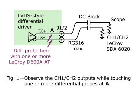
A trivial setup will suffice for this measurement. Take any driver and run its output directly into your scope with coaxial cables (no probes). Then, while observing the coaxial output, touch a probe onto the output pins of the driver. See what happens.
My setup incorporates an LVDS-style differential driver (Figure 1). The driver feeds a

short (1-in.) pair of microstrip traces. The traces go out through SMA connectors then through 24 inches of RG316 coaxial cables to a scope. At the scope, I connect DC blocking capacitors ahead of the 50-ohm scope inputs. Then I display the signal.
When doing this test, the expected result depends on the relation between the input impedance of the probe and the impedance of the circuit under test. Think of the circuit under test as a voltage generator with output voltage v[source] and output impedance
Z1. When loaded with a probe having impedance,say, Z2, the expected value of the measured signal should be, according to the resistor-divider theorem:
V[measured] = V[source] * (Z2 / (Z2+Z1)) [1]
I'm using a LeCroy D600A-AT 7.5 GHz differential probe with a differential DC input impedance of Z2=4000 ohms,
http://www.lecroy.com/tm/products/Probes/Differential/WaveLink/default.asp .
My 100-ohm differential circuit, terminated at both ends, has an effective differential driving-point impedance of 50 ohms. That happens because,from the perspective of the probe, it "sees" 100 ohms to the left, at the driver, in parallel with another 100 ohms to the right, at the scope. Two 100-ohm loads in parallel makes a 50-ohm differential driving point impedance.
Given those numbers, I expect this attenuation factor when connecting the probe:
A[expected] = (4000 / (4000+50)) = 0.988
The expected reduction should shrink the signal by only 1.2 percent, a tiny change. Let's try it.Figure 2 plots the results when measuring a National Semiconductor DS25BR100 driver. This high-powered driver is designed for long-distance
transmission applications. It incorporates transmit pre-emphasis, a feature that is turned off for this test. The figure shows the results of experiments conducted with zero, one and two LeCroy probes connected to the output terminals of the device. All
 /5
/5 
文章评论(0条评论)
登录后参与讨论