

1 SCOPE
This specification defines the performance characteristics and production test requirement for BBU
2 GENERAL REQUIREMENT
Emerson Turn-key BBU is a backup power which designed under the request of client “Emerson”, it’s AC charge input voltage 176Vac~310Vac(45Hz-60Hz), Shall withstand 0-415VAC input damage. And provides 3000W output power,12V±1% output voltage and 250A±10A current.
3 MATERIAL AND CONSTRUCTION REQUIREMENTS
4 ELECTRICAL SPECIFICATIONS
4.1 AC-DC charger
4.1.1 AC Input voltage range: 176Vac~315Vac(45Hz-60Hz)
4.1.2 Input power range: 0~100W
4.1.3 Start up time: 5-8s
4.1.4 AC input current: 0.85A max at 176V
4.1.5 Inrush current: 10A max
4.1.6 THD: 15% max at 10%-100% load
4.1.7 PF: >0.95 at full load
4.1.8 AC input UVP: 133V±10V recovery: 160V±10V
4.1.9 AC input OVP: 360V±10V recovery: 350v±10V
4.1.10 AC output max voltage: 17.5V±0.7V
4.1.11 Charge output voltage: 12V-16.8V
4.1.12 Charge current: 1.2A-5A
4.1.13 Charge time: 3 hours max
4.1.14 Charge efficiency: >91%
4.2 Output voltage : 12V±0.01V
4.3 Output current: 250A±5%
4.4 Output power: 3KW@0C to +45C for 90 seconds
4.5 AC Leakage Current:3.5mA max
4.6 Discharge efficiency: >96%
4.7 Electrostatic Discharge (ESD)
EN61000-4-2:1995 Level 4, +/-8kV Contact and +/-15kV Air Discharge
4.8 Temperature and Humidity
4.4.1 Temperature
4.4.1.1 Operation temperature range:0°C to 45°C
4.4.1.2 Storage temperature range:
50% SOC and 85% max RH:
1 year storage for environment -20C to 25 C.
3 months storage for environment -25C to -20C or to 25 C to 40 C,.
1 week storage for environment -40C to -25C or 40 C to 60 C
4.4.2 Humidity
Relative Humidity, non-condensing: 0%-90%
5 PCBA Function Test
5.1 PCBA test diagram
Figure_1 DC-DC converter board PCBA test diagram

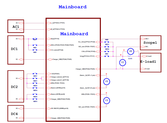
Figure_2 Mainboard board PCBA test diagram

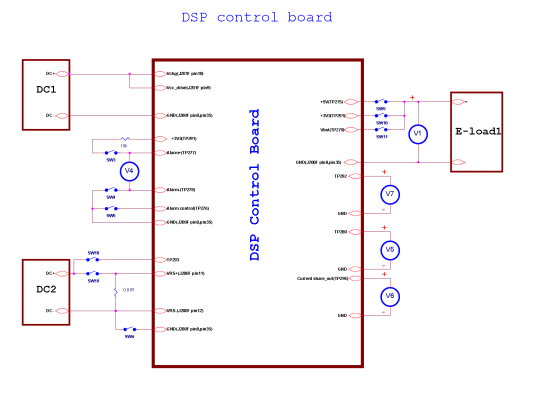
Figure_3 DSP control board PCBA test diagram

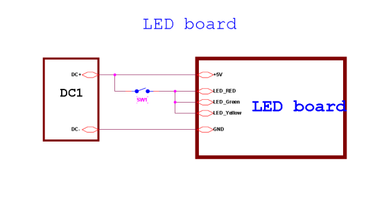
Figure_4 LED board PCBA test diagram
5.2 PCBA functional test
5.2.1 DC-DC converter board(55693-102) PCBA function test
Equipment list
◆ E-load2: >20V@40A
◆ DC3: >20V@50A
Test step
Note:
*Must short the S-GND and GND on the DC-DC converter board(The wire about 1cm)
*Turn off all equipment and switch before the test begin
 /4
/4 
文章评论(0条评论)
登录后参与讨论