

技术规范
功能描述:
实现一个由一条主干道和一条支干道的汇合点形成的十字路口的交通灯控制器,具体功能:
(1) 主、支干道各设有一个绿、黄、红指示灯,两个显示数码管。
(2) 主干道处于长允许通行状态,而支干道有车来时才允许通行。当主干道允许通行亮绿灯时,支干道亮红灯。而支干道允许通行亮绿灯时,主干道亮红灯。
(3) 当主干道、支干道均有车时,两者交替允许通行,主干道每次通行45 秒,支干道每次通行25 秒,在每次由绿灯向红灯转换的过程中,要亮5 秒的黄灯作为过渡,并进行减计时显示。
每个周期结束时都要进行支干道是否有车的检测,若有车则进行下一个周期,若没有,则主干道亮绿灯,支干道亮红灯,直到检测到支干道有车。
系统总体框图:
根据设计要求和系统所具有的功能,并参考相关的文献资料,经行方案设计,可以画出如下图所示的交通信号灯控制器的系统框图。
图二:系统总体框图
I/O管脚的描述
名称 | 方向 | 电平 | 位宽 | 功能 |
clk | Input | 3.3V | 1 | 系统时钟信号(10KHZ) |
car | Input | 3.3V | 1 | 检测信号 |
rst | Input | 3.3V | 1 | 复位信号 |
led | Output | 3.3V | 6 | LED灯 |
sel | Output | 3.3V | 7 | 数码管段码 |
seg | Output | 3.3V | 4 | 数码管位码 |
表一:系统总体I/O管脚的描述
注:其中系统时钟的频率选为10KHZ,复位采取同步复位方式,且低有效。支干道检测到有车时, car=1;否则,car=0。
方案对比:在交通灯控制器的设计中,交通灯控制及计时模块是本设计的关键模块。这个模块的实现可以用状态机,也可以用if—else语句来写。相比较而言,用状态机来写比较清楚明白直观,且容易避免出现未知状态。所以选用状态机来写此模块。
拟选用的FPGA类型:ep1cq240c8n
总体设计方案
交通灯
一、
系统详细框图
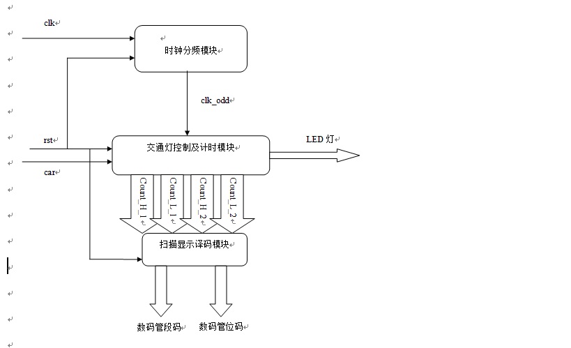
在系统总体框图的基础上进一步详细设计,得到如下系统详细框图。
图三:系统详细框图
注:系统总体I/O管脚描述请查看技术规范。
二、
具体模块设计
1.时钟分频模块
系统的动态扫描需要10KHZ的脉冲,而系统时钟计时模块需要1HZ的脉冲。分频模块主要为系统提供所需的时钟计时脉冲。该模块将10KHZ的脉冲信号进行分频,产生1S的方波(占空比为50%),作为系统时钟计时信号。
图四:时钟分频模块框图
I/O管脚描述如下:
名称 | 方向 | 电平 | 位宽 | 功能 |
clk | input | 3.3V | 1 | 系统时钟(10KHZ) |
rst | input | 3.3V | 1 | 复位信号 |
clk_odd | output | 3.3V | 1 | 分频后时钟信号(1HZ) |
表二:时钟分频模块I/O端口描述
注:系统时钟的频率为10KHZ,分频后的时钟信号为1HZ(占空比为50%)。复位信号为同步复位,且低有效。
2.交通灯控制及计时模块
控制模块根据外部输入信号和计时模块产生的输出信号,产生系统的状态机,控制其他部分协调工作。计时模块用来设定主干道和支干道计时器的初值,并为扫描显示译码模块提供倒计时时间。
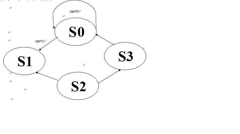
控制模块采用状态机进行设计,可以定义出5种状态,分别为S0:主干道绿灯,支干道红灯且没有车辆行驶;S1:主干道绿灯,支干道红灯且支干道有车辆驶入;S2:主干道黄灯,支干道红灯;S3:主干道红灯,支干道绿灯;S4:主干道红灯,支干道黄灯。利用CASE语句定义状态的转换方式及时间的变换方式,达到主干道绿灯亮45秒,支干道绿灯亮25秒,黄灯亮5秒的设计要求。
图五:交通灯控制及计数模块
I/O管脚描述如下:
名称 | 方向 | 电平 | 位宽 | 功能 |
clk_odd | Input | 3.3V | 1 | 分频后时钟信号(1HZ) |
rst | Input | 3.3V | 1 | 复位信号(同步复位) |
car | Input | 3.3V | 1 | 检测信号(低有效) |
count_H_1 | Output | 3.3V | 4 | 主干道时间高位译码 |
count_L_1 | Output | 3.3V | 4 | 主干道时间低位译码 |
count_H_2 | Output | 3.3V | 4 | 支干道时间高位译码 |
count_L_2 | Output | 3.3V | 4 | 支干道时间低位译码 |
led | Output | 3.3V | 6 | LED灯 |
表三:交通灯控制模块I/O端口描述
系统状态流程图:

S0:主干道绿灯,支干道红灯
S1:主干道黄灯,支干道红灯
S2:主干道红灯,支干道绿灯
S3:主干道红灯,支干道黄灯
3.扫描显示译码模块
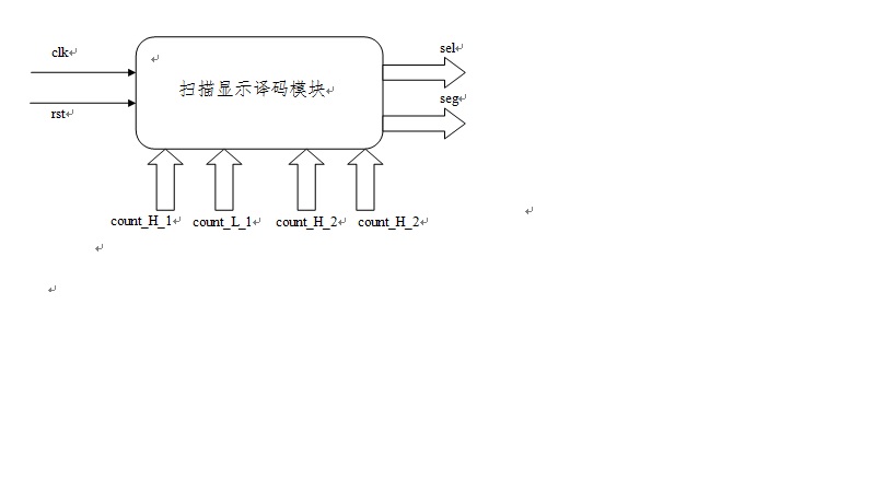
扫描显示译码模块可以根据控制信号,驱动交通信号灯以及倒计时数码管的显示,其中数码管的显示采用动态扫描显示。

图六:扫描显示译码模块框图
该模块的I/O管脚描述如下:
名称 | 方向 | 电平 | 位宽 | 功能 |
clk | Input | 3.3V | 1 | 系统时钟信号(10KHZ) |
rst | Input | 3.3V | 1 | 复位信号(低有效) |
count_H_1 | Input | 3.3V | 4 | 主干道时间高位译码 |
count_L_1 | Input | 3.3V | 4 | 主干道时间低位译码 |
count_H_2 | Input | 3.3V | 4 | 支干道时间高位译码 |
count_L_2 | Input | 3.3V | 4 | 支干道时间低位译码 |
sel | Output | 3.3V | 7 | 数码管段码 |
seg | Output | 3.3V | 3 | 数码管位码 |
表四:扫描显示译码模块I/O端口描述
附件:源代码:
分频模块:
module fenpinqi(clk,rst,clk_odd);
input clk,rst;
output clk_odd;
reg clk_odd;
reg[13:0] count;
parameter N = 10000;
always @ (posedge clk)
if(! rst)
begin
count <= 1'b0;
clk_odd <= 1'b0;
end
else
if ( count < N/2-1)
begin
count <= count + 1'b1;
end
else
begin
count <= 1'b0;
clk_odd <= ~clk_odd;
end
endmodule
控制及计时模块:
module control(led,car,rst,clk,count_H_1,count_L_1,count_H_2,count_L_2);
output
[3:0]count_H_1,count_L_1,count_H_2,count_L_2;
output [5:0]led;
input clk,rst,car;
reg [5:0] led;
reg
[3:0]count_H_1,count_L_1,count_H_2,count_L_2;
reg [1:0]state;
parameter S0=2'b00,
S1=2'b01,
S2=2'b10,
S3=2'b11;
always @(posedge clk or negedge
rst)
if(!rst)
begin
led=6'b010100;
state=S0;
count_H_1=4'b0000;count_L_1=4'b0000;
count_H_2=4'b0000;count_L_2=4'b0000;
end
else
begin
case(state)
S0:
begin
if(!car)
begin
led=6'b010100;
count_H_1=4'b0100;count_L_1=4'b0101;
end
else
if(count_L_1==0)
begin
if(count_H_1==0)
begin
led=6'b001100;
count_H_1=4'b0000;count_L_1=4'b0100;
state<=S1;
end
else
begin
count_H_1<=count_H_1-1'b1;
count_L_1<=4'b1001;
end
end
else begin
count_L_1<=count_L_1-1'b1;
// count_L_2<=count_L_2-1'b1;
end
if(!car)
begin
count_H_2=4'b0101;count_L_2=4'b0000;
end
else if(count_L_2==0)
begin
count_H_2<=count_H_2-1'b1;
count_L_2<=4'b1001;
end
else begin
count_L_2<=count_L_2-1'b1;
end
end
S1:
begin
if(count_L_1==0)
begin
if(count_H_1==0)
begin
led=6'b100010;
count_H_1=4'b0010;count_L_1=4'b1001;
count_H_2=4'b0010;count_L_2=4'b0100;
state<=S2;
end
else begin
count_H_1<=count_H_1-1'b1;
count_H_2<=count_H_2-1'b1;
end
end
else begin
count_L_1<=count_L_1-1'b1;
count_L_2<=count_L_2-1'b1;
end
end
S2:
begin
if(count_L_2==0)
begin
if(count_H_2==0)
begin
led=6'b100001;
count_H_2=4'b0000;count_L_2=4'b0100;
state<=S3;
end
else begin
count_H_2<=count_H_2-1'b1;
count_L_2=4'b1001;
end
end
else begin
count_L_2<=count_L_2-1'b1;
end
if(count_L_1==0)
begin
begin
count_H_1<=count_H_1-1'b1;
count_L_1=4'b1001;
end
end
else begin
count_L_1<=count_L_1-1'b1;
end
end
S3:
begin
if(count_L_2==0)
begin
if(count_H_2==0)
begin
led=6'b010100;
count_H_1=4'b0100;count_L_1=4'b1001;
count_H_2=4'b0100;count_L_2=4'b0100;
state<=S0;
end
else begin
count_H_1<=count_H_1-1'b1;
count_H_2<=count_H_2-1'b1;
end
end
else
begin
count_L_1<=count_L_1-1'b1;
count_L_2<=count_L_2-1'b1;
end
end
endcase
end
endmodule
扫描译码显示模块:
module saomiao(rst,clk,count_H_1,count_L_1,count_H_2,count_L_2,sel,seg);
input rst,clk;
input
[3:0]count_H_1,count_L_1,count_H_2,count_L_2;
output [6:0]sel;
output [3:0]seg;
reg [6:0]sel;
reg [3:0]seg;
reg [15:0] count;
reg [1:0] cnt;
reg
[3:0] data;
reg clk_odd;
always@(posedge clk or negedge
rst)//50M-1k,50M/1k/2//??,50Mhz~1khz,???50%
begin
if(!rst)begin
count<=0;
clk_odd<=0;
end
else if(count==16'd2)
begin
clk_odd<=~clk_odd;
count<=0;
end
else
count<=count+1'b1;
end
always @(negedge rst or posedge clk_odd)//????1ms
if (!rst)begin
cnt<=2'b00;
end
else cnt<=cnt+1'b1;
always@(negedge rst or posedge clk)
//????
if(!rst) begin
// sel = 7'b0000000 ;
seg = 4'b1111 ;
end
else begin
case (cnt)
2'b00: begin
seg =4'b1110 ;// ?????
data=count_H_1;
end
2'b01: begin
seg = 4'b1101 ;// ?????
data =count_L_1;
end
2'b10:begin // ?????
seg= 4'b1011 ;
data=count_H_2;
end
2'b11: begin// ?????
seg= 4'b0111 ;
data=count_L_2;
end
default :
begin
// sel = 8'b0000000 ;
seg = 4'b0000 ;
end
endcase
end
always @ (data or seg)begin
case(data)
4'b0000:sel=7'b1111110;
4'b0001:sel=7'b0110000;
4'b0010:sel=7'b1101101;
4'b0011:sel=7'b1111001;
4'b0100:sel=7'b0110011;
4'b0101:sel=7'b1011011;
4'b0110:sel=7'b1011111;
4'b0111:sel=7'b1110000;
4'b1000:sel=7'b1111111;
4'b1001:sel=7'b1111011;
default:sel=7'b1111110;
endcase
end
endmodule
顶层模块:
module jiaotongdeng(clk,rst,car,led,sel,seg);
input clk,rst,car;
output [3:0] seg;
output [6:0] sel;
output [5:0] led;
wire [3:0]count_H_1,count_L_1,count_H_2,count_L_2;
wire clk_odd;
saomiao ee(rst,clk,count_H_1,count_L_1,count_H_2,count_L_2,sel,seg);
control rr(led,car,rst,clk_odd,count_H_1,count_L_1,count_H_2,count_L_2);
fenpinqi tt(clk,rst,clk_odd);
endmodule
 /3
/3 
文章评论(0条评论)
登录后参与讨论