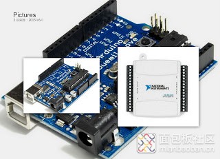


所需的硬體以及軟體如下:
Arduino UNO | |
USB to TTL | |
Arduino IDE | |
USB to TTL驅動程式 | |
LABVIEW | 2011年版本。 |

這一個Project 最主要的目的是要使用Arduino取代NI USB6501 的DAQ
使用Arduino的方案可以節省許多成本。
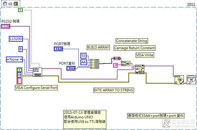
Labview主程式碼如下圖:

步驟:
1. 建立Arduino的串列埠使他可以透過RS232通信界面藉由USB to TTL跟LABVIEW溝通。
所需的設定如下:
在這個專案中我設定的鮑率是每秒115200 bits
2. 撰寫 與LABVIEW通信的函數

Receive_data :接受來自於LABVIEW的通信命令。
Test_do_data : 處理命令的工作。
/*
Program by Lee Chin Wei
Date : 2015-06-29
這是使用Labview 控制Arduino 來取代NI 的DAQ
Port D 為輸出數位IO
prot C 為類比輸入IO
通信格式:
0x55,0xAA,0xXX,0xXX
*/
#include
//#include // IIC communication
//#include // LCD
//#define A0_Command 0x10 //A0采集命令字
//#define A1_Command 0x11 //A1采集命令字
//#define D0_Command 0x20 //D0采集命令字
//#define D1_Command 0x21 //D1采集命令字
#define portb_output 0x0b
#define portc_input 0x0c
#define portd_output 0xd
byte comdata[4]={0}; //定义数组数据,存放串口接收数据
int AD_Value=0; //AD转换后的数字量
float float_AD_Value; //数字量换算成浮点电压量
int D_Value=0; //数字量测量的数据
byte PB_data = 0;
byte PD_data = 0;
byte PC_data = 0;
byte PCACK = 0;
byte comport = 0;
byte pdata = 0;
//LiquidCrystal_I2C lcd(0x27, 2, 1, 0, 4, 5, 6, 7, 3, POSITIVE); // Set the LCD I2C address定義LCD的腳位
void receive_data(void); //接收串列資料
void test_do_data(void); //測試串列資料是否正確並更新資料
void setup()
{
// lcd.begin(16,2); // initialize the lcd for 20 chars 4 lines, turn on backlight
// lcd.backlight(); //點亮背光
// Print a message to the LCD.
// lcd.setCursor(2, 0); //設定游標在第2列第0行
// lcd.print("Reset!! ");
// lcd.setCursor(2, 1);
// lcd.print(" "); // show the Jig version
//delay(2000); //延遲2秒
//lcd.clear();
Serial.begin (115200); //(9600);
// pinMode(2, INPUT);
// pinMode(3, INPUT);
DDRB = 0b00111111;
DDRC = 0x00;
DDRD = 0b11111100;
// DDRD = 0xFF; //setting for output
// PORTD = 0xFF; // PORTD OUTPUT 0XFF HIGHT
}
void loop()
{
// digitalWrite (8,HIGH);
if (Serial.available() > 0 ) //不斷的檢查串列埠是否有資料
{
// PCACK = Serial.read();
// if (PCACK == 0x12)
// {
// lcd.setCursor(2, 0); //設定游標在第2列第0行
// lcd.print(PCACK);
// Serial.println(0x34);
// digitalWrite (8,LOW);
receive_data(); //接收串列的資料
test_do_data(); //測試資料是否正確並更新
// }
}
}
void receive_data(void)
{
int i ;
for(i=0;i < 4;i++)
{
// while (Serial.available() == 0);
comdata =Serial.read(); //將RS232資料讀進buffer 共4bytes
//延遲一下,讓串列暫存器準備下一個位元,如果不延遲可能會導致資料遺失。
delay(2);
}
comport = comdata[2];
pdata = comdata[3];
// lcd.setCursor(5, 1); //設定游標在第2列第0行
// lcd.print(comport);
// lcd.setCursor(7, 1); //設定游標在第2列第0行
// lcd.print(pdata);
}
void test_do_data(void)
{
if ((comdata[0] == 0x55)&&(comdata[1] ==0xAA))
{
// digitalWrite(8,HIGH);
switch (comport)
{
case portb_output : // portb for output
{ PB_data = pdata;
PORTB = PB_data; //
// lcd.setCursor(0, 1); //設定游標在第2列第0行
// lcd.print(1);
// Serial.println(0x34);
break;
}
case portc_input :
{ PC_data = pdata;
PORTC = PC_data; //comdata[3];
// lcd.setCursor(1, 1); //設定游標在第2列第0行
// lcd.print(2);
// Serial.println(0x34);
break; }
case portd_output :
{ PD_data = pdata;
PORTD = PD_data;
// digitalWrite (8,LOW);
// Serial.println(0x34);
//lcd.setCursor(2, 1); //設定游標在第2列第0行
//lcd.print(3);
break; }
defualt :
{
// lcd.setCursor(3, 1); //設定游標在第2列第0行
// lcd.print("Defual");
// Serial.println(0x34);
break;}
}
} //if comdata == 0x55&& 0xAA
}
 /1
/1 
dongle_740206724 2019-1-17 17:07