原创
如何用一条I2C总线驱动多个I2C设备?
2022-5-24 08:32
7934
14
4
分类:
智能硬件
文集:
方案
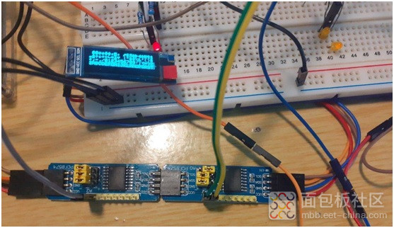
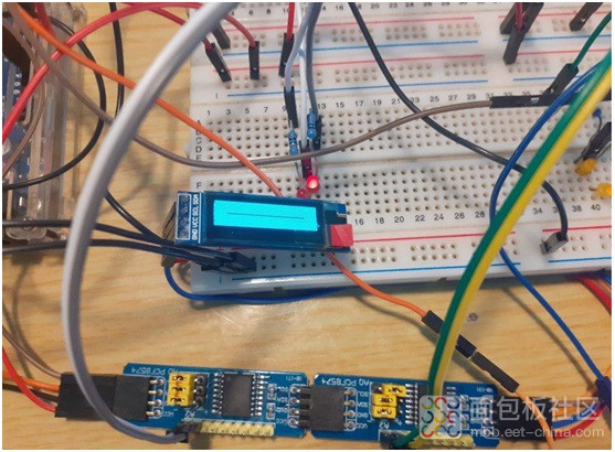
应用设计中,用一条I2C总线驱动多个I2C设备师很常见,实施也很简单,本项目将连接以下I2C设备:
1x16×2 I2C LCD显示屏,地址0x27
1x 128×32 I2C OLED显示屏,地址0x3C
2x PCF8574 I2C Io扩展器,地址0x20、0x21
上述组件可使用以下库文件,通过Arduino Uno控制:
LiquidCrystal_I2C.h,控制LCD屏;
Wire.h and PCF8574.h,控制I2C IO扩展器;
Adafruit_GFX, Adafruit_SSD1306.h 和 SPI.h,控制SSD1306 128×32 OLED显示屏。
由于所有元件相距不远,没必要I2C总线使用上拉电阻,因为这些杜邦线就是组件的一部分。
本项目电路很直观,不同的是,Uno板子在顶部靠近USB适配器附近增加了一个I2C口,我们把它和A4、A5一起使用。
首先,将所有I2C组件的SDA引脚以串行方式连接在一起,再连接于Arduino SDA引脚(一般为A4)。
其次,将所有I2C组件的SCL引脚串联起来,再连接到Arduino SCL引脚(一般为A5)
第三,将所有5v(Vcc)引线连接到Arduino开发板的5v引脚,所有接地引线(GND)连接到Arduino板子的GND引脚。
第四,通过阻值在640-1000欧姆范围内的电阻,将4个LEDs的一个引脚连接到两个PCF8574 IO扩展器P0、P1引脚,另一个引脚接地。
本项目采用外接的5v电源供电,因为根据Uno的实际需求,没必要从稳压器获得太大的电流。
连接完成后,检查所有接线,再打开Arduino IDE中的i2c扫描工具,就会再示例中看到库 Wire.h 文件。
启动电源,将库文件上传到Uno,再打开Serial Monitor,就会看到检测到了4个I2C设备。
如果没有检测到4个设备,检查接线和设备地址,看看问题出在哪里,很有可能是接线问题,或者设备的地址错了。
如果一切无误,将以下代码拷入Arduino IDE,相关解释参见中间的注释。
/*
Multiple devices on the I2C bus Maker and Iot Ideas, MakerIoT2020*/// Include the libraries that we will need#include // needed for OLED display. #include // PCF8574#include // Generic I2C library#include // for OLED display#include // for OLED display#include // For I2C LCD display// we need to define the size of the OLED screen#define OLED_WIDTH 128#define OLED_HEIGHT 32// mine does not have an onboard reset pin. If yours do, specify the // pin that it is connected to on the Arduino here. To use the // Arduino reset pin, specify -1 as below#define OLED_RESET -1// Define the OLED display, width,hight protocol and reset pinAdafruit_SSD1306 oled(OLED_WIDTH,OLED_HEIGHT, &Wire, OLED_RESET);// Define the I2C LCD screen address and pin configurationLiquidCrystal_I2C lcd(0x27,2,1,0,4,5,6,7,3,POSITIVE);// Define the PCF8574 devices ( you can have up to 8 on a bus )// but in this case, my LCD uses address 0x27, so I will have a // conflicting address if I were to use 8 of them together with the// LCDPCF8574 Remote_1(0x20); PCF8574 Remote_2(0x21);// Note the I2C addresses. You can obtain them from the i2c_scannervoid setup() { // serial debugging if needed Serial.begin(115200); // Start OLED Display Init if (!oled.begin(SSD1306_SWITCHCAPVCC,0x3C)) { // Init the OLED Serial.println(F("OLED INIT FAILED")); for(;;); // Dont proceed ... loop forever } oled.display(); delay(2000); // This delay is required to give display time to // initialise properly oled.clearDisplay(); oled.setTextSize(0); oled.setTextColor(SSD1306_WHITE); oled.setCursor(0,0); oled.println("TEST SCREEN"); oled.display(); delay(2000); oled.clearDisplay(); oled.setCursor(1,0); oled.println("OLED SCREEN ON"); oled.display(); // Start the LCD lcd.begin(16,2); // Set the initial state of the pins on the PCF8574 devices // I found that the PCF8574 library sometimes does funny things // This is also an example of how to use native i2c to set the // status of the pins Wire.begin(); Wire.beginTransmission(0x20); // device 1 Wire.write(0x00); // all ports off Wire.endTransmission(); Wire.begin(); Wire.beginTransmission(0x21); // device 2 Wire.write(0x00); // all ports off Wire.endTransmission(); // Set pinModes for PCF8574 devices // Note that there are two of them Remote_1.pinMode(P0,OUTPUT); Remote_1.pinMode(P1,OUTPUT); Remote_2.pinMode(P0,OUTPUT); Remote_2.pinMode(P1,OUTPUT); // Start both IO extenders Remote_1.begin(); Remote_2.begin(); // and set ports to low on both // you may find that if you ommit this step, they come up in an // unstable state. Remote_1.digitalWrite(P0,LOW); Remote_1.digitalWrite(P1,LOW); Remote_2.digitalWrite(P0,LOW); Remote_2.digitalWrite(P1,LOW); }void loop() { // Draw a character map on the OLED display. // This function is borrowed from the Adafruit library testdrawchar(); // Write to the IO extenders Remote_1.digitalWrite(P0,HIGH); Remote_1.digitalWrite(P1,LOW); Remote_2.digitalWrite(P0,HIGH); Remote_2.digitalWrite(P1,LOW); // Display their status on the LCD lcd.setCursor(0,0); lcd.print(" R1 P0=1 P1=0"); lcd.setCursor(0,1); lcd.print(" R2 P0=1 P1=0"); delay(500); // Change status Remote_1.digitalWrite(P1,HIGH); Remote_1.digitalWrite(P0,LOW); Remote_2.digitalWrite(P1,HIGH); Remote_2.digitalWrite(P0,LOW); // Update LCD lcd.setCursor(0,0); lcd.print(" R1 P0=0 P1=1"); lcd.setCursor(0,1); lcd.print(" R2 P0=0 P1=1"); delay(500); // Do some graphics on the OLED display // Function borrowed from Adafruit testdrawrect(); oled.clearDisplay(); delay(500); // repeat indefinitely}void testdrawrect(void) { oled.clearDisplay(); for(int16_t i=0; i oled.drawRect(i, i, oled.width()-2*i, oled.height()-2*i, SSD1306_WHITE); oled.display(); // Update screen with each newly-drawn rectangle delay(1); } delay(500);}void testdrawchar(void) { oled.clearDisplay(); oled.setTextSize(1); // Normal 1:1 pixel scale oled.setTextColor(SSD1306_WHITE); // Draw white text oled.setCursor(0, 0); // Start at top-left corner oled.cp437(true); // Use full 256 char 'Code Page 437' font // Not all the characters will fit on the display. This is normal. // Library will draw what it can and the rest will be clipped. for(int16_t i=0; i<256; i++) { if(i == '\n') oled.write(' '); else oled.write(i); } oled.display(); delay(500);}复制代码
作者: 硬之城Allchips, 来源:面包板社区
链接: https://mbb.eet-china.com/blog/uid-me-3975615.html
版权声明:本文为博主原创,未经本人允许,禁止转载!


 /2
/2 


文章评论(0条评论)
登录后参与讨论