


http://www.cnblogs.com/oomusou/archive/2008/07/09/modelsim_altera_tutorial.html
Abstract
在Quartus II雖然可以用Vector Waveform的方式作電路模擬,不過這僅限於簡單的模擬,該如何用ModelSim-Altera配合testbench來做較複雜的電路模擬呢?
Introduction
使用環境:Quartus II 7.2 SP3 + ModelSim-Altera 6.1g
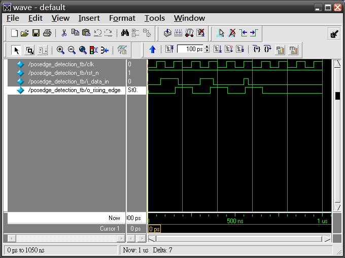
在(筆記) 如何設計邊緣檢測電路? (SOC) (Verilog),我們使用了Quartus II內建的vector waveform來模擬,可以使用GUI介面來指定波形,非常方便,對於小電路來說,這種拖拖拉拉的方式還算順手,但大電路還是得靠Verilog來寫testbench,然後配合ModelSim做模擬。本篇使用(筆記) 如何設計邊緣檢測電路? (SOC) (Verilog)的上升沿檢測電路(posedge detection circuit),並加上testbench搭配ModelSim-Altera做模擬。
Step 1:
posedge_detection_tb.v / Verilog
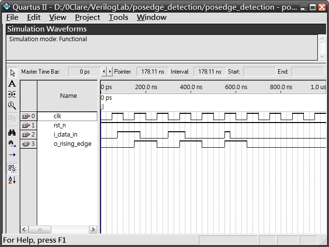
使用testbench描述出如下在vector waveform中的波形
Step 2:
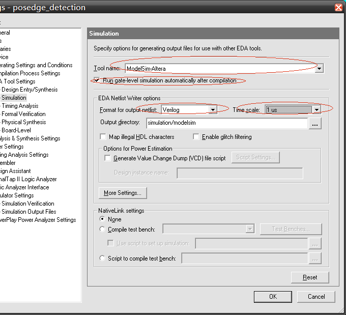
設定Quartus II使用ModelSim-Altera模擬
Assignments -> Settings -> Category :EDA Tool Settings -> Simulation:
Tool name:ModelSim-Altera
選取Run gate-level simulation automatically after compilation
Format for output netlist:Verilog
Time scale:1 us
Step 3:
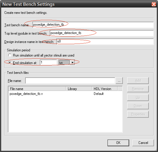
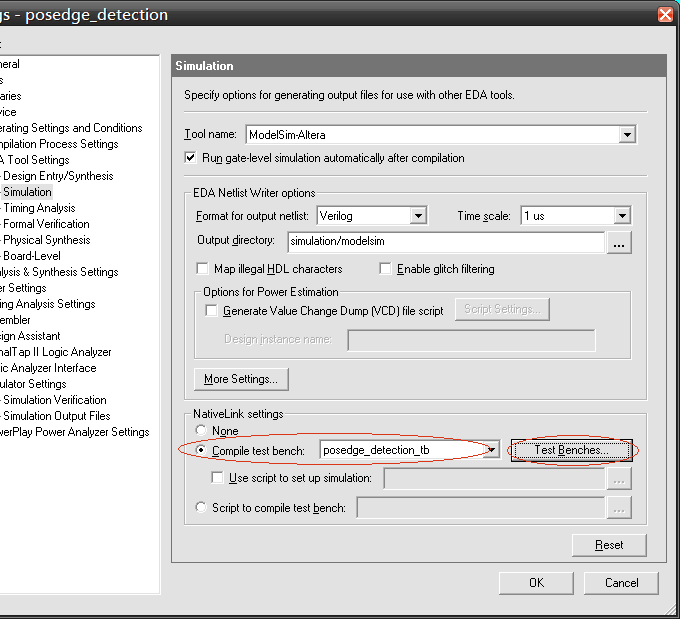
設定testbench
在同一頁的NativeLink settings選擇Compile test bench,按下TestBenches..加入posedge_detection_tb.v。比較詭異的是,Test bench name、Top level module in test bench與Design instance name in test bench無法自己抓到,必須自己填。
Step 4:
編譯並模擬
Processing -> Start Compilation
 /3
/3 
文章评论(0条评论)
登录后参与讨论