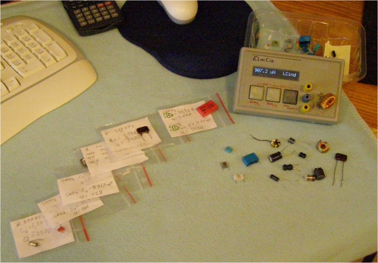
Both methods were merged by me, resulting in the Elmcie design:
Elsie's mechanism (resonance-circuit) is great for small capacitances and inductors,
where Elm-Chan's capacitance meter (based on RC-time-measurement) is more suitable for large capacitors,
especially electrolytes, upto 2200 uF.
Implementation of algorythms are all genuine Plonswerk :-)
This software is published under GNU General Public License (enclosed in the package)
Plons on AVRfreaks.net (Nard Awater), April 29, 2008
Update
If you need to contact me on Elmcie, then do what spambots cannot:
Take the typenumber of the comparator in the device that is discussed here, then take that curly symbol as we find in all emailaddresses, and take then the domain-name you find right now in the address-bar of your browser. The nicer address elmcie@ etc is absorbed in spambot-universe, so all that mail goes "linea recta" to the spambox.
Copyright (C) 2007 Nard Awater
This program is free software; you can redistribute it and/or
modify it under the terms of the GNU General Public License
as published by the Free Software Foundation; either version 2
of the License, or (at your option) any later version.
This program is distributed in the hope that it will be useful,
but WITHOUT ANY WARRANTY; without even the implied warranty of
MERCHANTABILITY or FITNESS FOR A PARTICULAR PURPOSE. See the
GNU General Public License for more details.
A copy of the GNU General Public License is posted here and has to
stay with this program; if it cannot be found, write to the Free Software Foundation,
Inc., 59 Temple Place - Suite 330, Boston, MA 02111-1307, USA.
The complete BascomAVR software package can be downloaded here
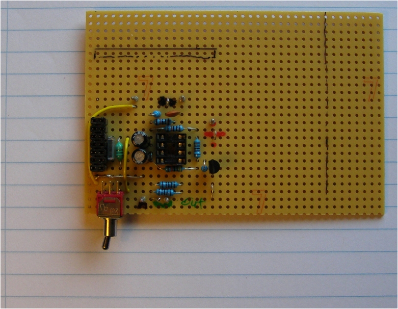
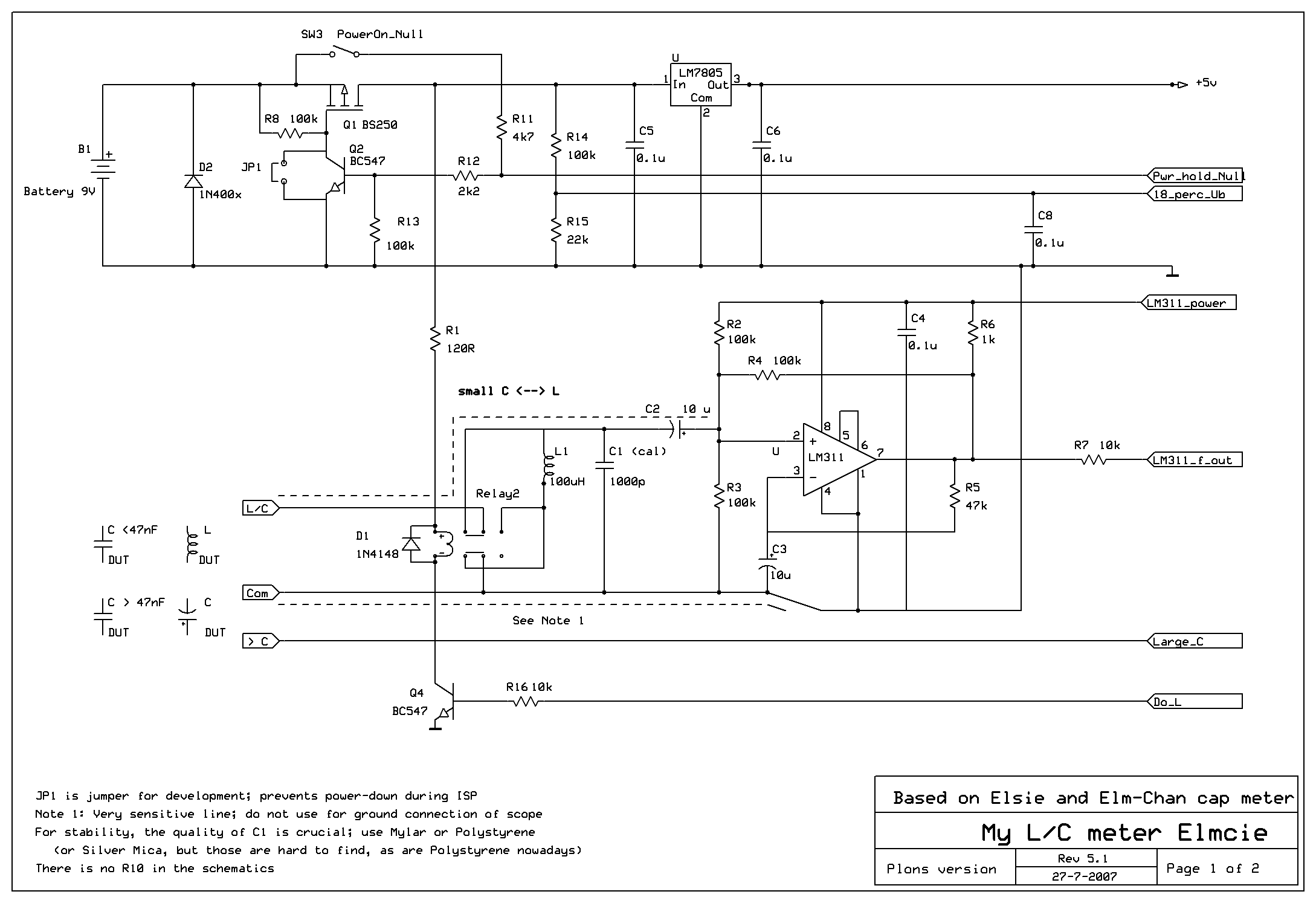
The schematics in .png-format:
Left-click to view in full size, Right-click to download in full size
Notes on Elmcie @ rev 5.1 schematics and rev 2.0 Software:
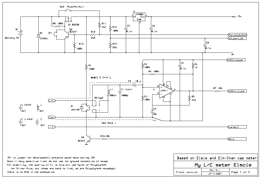
Schematic sheet 1 of 2:
1. The power for the relay is derived from the 9V supply. If you use a 5V-relais, R1 can be omitted and the 5V can be used instead.
2.Keep the lines between the LM311 inputs and the connector where you connect the DUT to, as short as possible. The same applies for the Large_C-line.
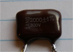
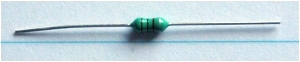
Use a good capacitor for C1, f.i. a polystyrene like this one
If you can find a silver-mica .... that would be even better
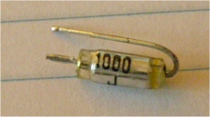
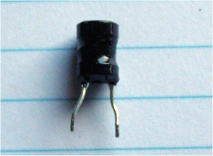
For the inductor L1 the same applies.
A small one like this one
was tested and found to be okay by other users.
My experience with it was not that good, so I used this one in the final build:
3. You may use a 78L05 (the small version) instead of the 7805, but bear in mind that it will get warm. You can reduce that by powering the relay form the 9V (as I did), and powering the backlight of the LCD from the 9V. Be carefull though .... 9V is deadly for the LCD and the AVR.
4. Read the notes in the schematic please :-)
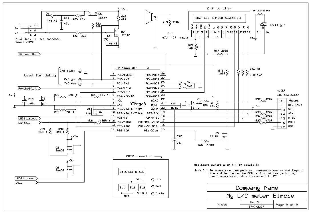
Schematic sheet 2 of 2:
5. If you write your own software, or adapt mine, consider to skip the backlight-boost (PortB.1). Elmcie is a battery powered device, and I found that one standard setting is sufficient. Doing so frees portB.1 . You can use it to control the LM311_power from a separate pin. (note that LM311_power-control and the 3k3 pull-up for Elm are now controlled by one pin )
6. The ISP-pins are used for the LCD-data, and omitting the 4k7 resistors R36-38 will cause problem during ISP. Also note that R9 pulls the E-signal for the LCD low to prevent ISP-errors.
7. The quasi RS232 interface in the upper left corner can be omitted or replaced with a Max232 or alike. In case your LCD requires a negative bias-voltage, it's recommendable to do so.
Software rev 2.0:
8. If you write your own software, read the ELMCIE2_0.rtf . There is quite some information in the comments which you will (or should I say: may ?) find to be usefull.
9. With the release of revision 2.0 I added a procedure that contains an instruction in .rtf-format, and in total 4 programs. No need to be alarmed ... it's not that bad :-)
Just unzip it, open 123_Elmcie_Pre-flight_instructions_R1.rtf
- Taras for testing rev 2 and the procedure; he also sent me a bunch of accurate capacitors to help Elmcie-builders to get a set of CalCaps
Update February 2, 2008:
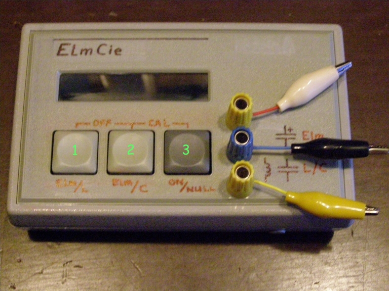
I didn't write an operators-manual for Elmcie, so here some guidance:
On schematic sht 2 of 2 is a function-description of the buttons. But not complete indeed.
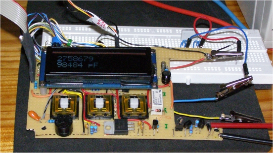
Refer to this picture:
Elmcie holds two instruments: a capacitance-meter based on ElmChan's design, and an LC-meter based in Elcie (or Elsie)
Since there were only three buttons available, it was necessary to do some tricks to get all necessary functions in.
When Elmcie is Off, Button3 is the ON-button. Once in on-state, it acts as Null-button.
Default it starts up in Elm-mode (reason for that is the lowest power-consumption)
To null it, press button3 again. Instructions are given in the display.
To calibrate Elm, press button2 and button3 simultaneously. Further instructions in the display
Elm-mode is auto-ranging; connect the DUT (Device Under Test) to the Elm-terminals.
To switch to Elcie-mode, press button1 for inductances, or button2 for capacitance. To Null or Cal: same as above, and again, instructions in the display.
No need to worry about making mistakes: the software checks if the validity of your actions. If out of expected range, it burps and displays the error-message.
Once in Elcie-mode you can switch back to Elm-mode by pressing button1 or button2, depending on where you are in Elcie.
The display informs you (as user) always where you are.
To turn Elmcie OFF, press and hold button1 and 2
All commands are provided with audio-feedback. You'll get used to it as the tones are self-explanatory.


 /5
/5 


文章评论(0条评论)
登录后参与讨论