

1. JTAG
JTAG方式下载SOF文件到FPGA,掉电后需要重新下载程序,适用于调试程序阶段。
(1) The pull-up resistor should be connected to the same supply voltage as the USB-Blaster, MasterBlaster (VIO pin), ByteBlaster II, or ByteBlasterMV cable.
(2) Connect the nCONFIG and MSEL[1..0] pins to support a non-JTAG configuration scheme. If only JTAG configuration is used, connect the nCONFIG pin to VCC, and the MSEL[1..0] pins to ground. In addition, pull DCLK and DATA0 to either high or low, whichever is convenient on your board.
(3) Pin 6 of the header is a VIO reference voltage for the MasterBlaster output driver. VIO should match the device’s VCCIO. Refer to the MasterBlaster Serial/USB Communications Cable Data Sheet for this value. In the ByteBlasterMV, this pin is a no connect. In the USB-Blaster and ByteBlaster II, this pin is connected to nCE when it is used for AS programming, otherwise it is a no connect.<?xml:namespace prefix = o ns = "urn:schemas-microsoft-com:office:office" />
(4) nCE must be connected to GND or driven low for successful JTAG configuration.
(5) The nCEO pin can be left unconnected or used as a user I/O pin when it does not feed other device’s nCE pin.
2. AS (Active Serial)
AS方式使用USB-Blaster? or ByteBlaster? II download cable下载POF文件到FPGA的配置芯片如EPCS系列,掉电后不需要重新下载程序。
Notes to Figure 13–3:
(1) Connect the pull-up resistors to a 3.3-V supply.
(2) Cyclone II devices use the ASDO to ASDI path to control the configuration device.
(3) The nCEO pin can be left unconnected or used as a user I/O pin when it does not feed another device’s nCE pin.
关于MSEL0,1的连接:
Notes to Tabl e 13–1:
(1) Only the EPCS16 and EPCS64 devices support a DCLK up to 40 MHz clock; other EPCS devices support a DCLK up to 20 MHz. Refer to the Serial Configuration Devices Data Sheet for more information.
(2) JTAG-based configuration takes precedence over other configuration schemes, which means MSEL pin settings are ignored.
(3) Do not leave the MSEL pins floating; connect them to VCCIO or ground. These pins support the non-JTAG configuration scheme used in production. If you are only using JTAG configuration, you should connect the MSEL pins to ground.
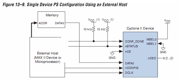
3. PS (Passive Serial)
使用外部的处理器或MAX芯片来配置FPGA,感觉比较麻烦。 .
.
Notes to Figure 13–9:
(1) Connect the pull-up resistor to a supply that provides an acceptable input signal for the device. VCC should be high enough to meet the VIH specification of the I/O on the device and the external host.
(2) The nCEO pin can be left unconnected or used as a user I/O pin when it does not feed other device’s nCE pin.
来源:Configuring Cyclone II Devices
Config Handbook (更为全面,包含所有Altera器件的配置方法)
 /5
/5 
用户1613217 2010-11-22 03:01