

上文:STM32 RVMDK学习实例第一篇
http://blog.ednchina.com/liongt/134672/message.aspx
STM32 RVMDK学习实例第二篇,用STM32的ADC采集模拟电压,转换结果以DMA方式传输给USART,USART通过串口发送到上位机。实验方法是先用RVMDK进行软件仿真,然后下载到开发板进行验证,所用的开发板是万利的EK-STM<?xml:namespace prefix = st1 ns = "urn:schemas-microsoft-com:office:smarttags" />32F。
<?xml:namespace prefix = o ns = "urn:schemas-microsoft-com:office:office" />
/* Includes ------------------------------------------------------------------*/
#include "main.h"
/* Private typedef -----------------------------------------------------------*/
/* Private define ------------------------------------------------------------*/
#define ADC1_DR_Address ((u32)0x4001244C)
/* Private macro -------------------------------------------------------------*/
/* Private variables ---------------------------------------------------------*/
vu16 ADC_ConvertedValue;
/* Private function prototypes -----------------------------------------------*/
void RCC_Configuration(void);
void GPIO_Configuration(void);
void USART_Config(void);
void DMA_Config(void);
void ADC_Config(void);
void Delay(vu32 nCount);
/* Private functions ---------------------------------------------------------*/
/******************************************************************************
* Function Name : main
* Description : Main program
* Input : None
* Output : None
* Return : None
*******************************************************************************
int main(void)
{
#ifdef DEBUG
debug();
#endif
RCC_Configuration();
GPIO_Configuration();
USART_Config();
DMA_Config();
ADC_Config();
while (1)
{
Delay(0xFFFFFF);
printf("ADC = %X Volt = %d mv\r\n", ADC_ConvertedValue, ADC_ConvertedValue*3300/4096);
}
}
/******************************************************************************
* Function Name : RCC_Configuration
* Description : Configures the different system clocks.
* Input : None
* Output : None
* Return : None
*******************************************************************************
void RCC_Configuration(void)
{
ErrorStatus HSEStartUpStatus; //定义外部高速晶体启动状态枚举变量
RCC_DeInit(); //复位RCC外部设备寄存器到默认值
RCC_HSEConfig(RCC_HSE_ON); //打开外部高速晶振
HSEStartUpStatus = RCC_WaitForHSEStartUp(); //等待外部高速时钟准备好
if(HSEStartUpStatus == SUCCESS) //外部高速时钟已经准备好
{
FLASH_PrefetchBufferCmd(FLASH_PrefetchBuffer_Enable);
FLASH_SetLatency(FLASH_Latency_2);
RCC_HCLKConfig(RCC_SYSCLK_Div1); //配置AHB(HCLK)时钟==SYSCLK
RCC_PCLK2Config(RCC_HCLK_Div1); //配置APB2(PCLK2)钟==AHB时钟
RCC_PCLK1Config(RCC_HCLK_Div2); //配置APB1(PCLK1)钟==AHB1/2时钟
RCC_PLLConfig(RCC_PLLSource_HSE_Div1, RCC_PLLMul_9);
RCC_PLLCmd(ENABLE); //使能PLL时钟
//等待PLL时钟就绪
while(RCC_GetFlagStatus(RCC_FLAG_PLLRDY) == RESET)
RCC_SYSCLKConfig(RCC_SYSCLKSource_PLLCLK); //配置系统时钟 = PLL时钟
//等待PLL时钟作为系统时钟
while(RCC_GetSYSCLKSource() != 0x08)
}
/* Enable DMA clock */
RCC_AHBPeriphClockCmd(RCC_AHBPeriph_DMA, ENABLE);
/* Enable ADC1 and GPIOC clock */
RCC_APB2PeriphClockCmd(RCC_APB2Periph_ADC1 | RCC_APB2Periph_GPIOC, ENABLE);
//打开GPIO和AFIO时钟
RCC_APB2PeriphClockCmd(RCC_APB2Periph_GPIOx | RCC_APB2Periph_AFIO, ENABLE);
//使能串口时钟
#ifdef USE_USART1
RCC_APB2PeriphClockCmd(RCC_APB2Periph_USART1, ENABLE);
#else
RCC_APB1PeriphClockCmd(RCC_APB1Periph_USARTx, ENABLE);
#endif
}
/******************************************************************************
* Function Name : GPIO_Configuration
* Description : Configures the different GPIO ports.
* Input : None
* Output : None
* Return : None
*******************************************************************************
void GPIO_Configuration(void)
{
GPIO_InitTypeDef GPIO_InitStructure; //定义GPIO初始化结构体
#ifdef USE_USART2
/* Enable the USART2 Pins Software Remapping */
GPIO_PinRemapConfig(GPIO_Remap_USART2, ENABLE); //使能GPIO端口映射USART2
#endif
// For STM3210B-LK1 configure PC.00 (ADC Channel10)
GPIO_InitStructure.GPIO_Pin = GPIO_Pin_0;
GPIO_InitStructure.GPIO_Mode = GPIO_Mode_AIN;
GPIO_Init(GPIOC, &GPIO_InitStructure);
/* Configure USARTx_Tx as alternate function push-pull */
GPIO_InitStructure.GPIO_Pin = GPIO_TxPin;
GPIO_InitStructure.GPIO_Speed = GPIO_Speed_50MHz; //引脚频率50M
GPIO_InitStructure.GPIO_Mode = GPIO_Mode_AF_PP;
GPIO_Init(GPIOx, &GPIO_InitStructure);
/* Configure USARTx_Rx as input floating */
GPIO_InitStructure.GPIO_Pin = GPIO_RxPin;
GPIO_InitStructure.GPIO_Mode = GPIO_Mode_IN_FLOATING; //设置Rx引脚为浮点输入模式
GPIO_Init(GPIOx, &GPIO_InitStructure);
}
/******************************************************************************
* Function Name : USART_Config(void);
* Description : Configures the USART ports.
* Input : None
* Output : None
* Return : None
*******************************************************************************
void USART_Config(void)
{
USART_InitTypeDef USART_InitStructure; //定义串口初始化结构体
USART_InitStructure.USART_BaudRate = 115200; //波特率115200
USART_InitStructure.USART_WordLength = USART_WordLength_8b; //8位数据
USART_InitStructure.USART_StopBits = USART_StopBits_1; //1个停止位
USART_InitStructure.USART_Parity = USART_Parity_No ; //无校验位
USART_InitStructure.USART_HardwareFlowControl = USART_HardwareFlowControl_None; //禁用RTSCTS硬件流控制
USART_InitStructure.USART_Mode = USART_Mode_Rx | USART_Mode_Tx; //使能接收/发送
USART_InitStructure.USART_Clock = USART_Clock_Disable; //串口时钟禁止
USART_InitStructure.USART_CPOL = USART_CPOL_Low; //时钟下降沿有效
USART_InitStructure.USART_CPHA = USART_CPHA_2Edge; //数据在第二个时钟沿捕捉
USART_InitStructure.USART_LastBit = USART_LastBit_Disable; //最后数据位的时钟脉冲不输出到SCLK引脚
USART_Init(USARTx, &USART_InitStructure); //初始化串口(USARTx在main.h中定义)
USART_Cmd(USARTx, ENABLE); //串口使能
}
/******************************************************************************
* Function Name : PUTCHAR_PROTOTYPE
* Description : Retargets the C library printf function to the USART.
* Input : None
* Output : None
* Return : None
*******************************************************************************
PUTCHAR_PROTOTYPE
{
/* Write a character to the USART */
USART_SendData(USARTx, (u8) ch);
/* Loop until the end of transmission */
while(USART_GetFlagStatus(USARTx, USART_FLAG_TXE) == RESET)
{
}
return ch;
}
/******************************************************************************
* Function Name : DMA_Config(void);
* Description : Configures the DMA.
* Input : None
* Output : None
* Return : None
*******************************************************************************
void DMA_Config(void)
{
DMA_InitTypeDef DMA_InitStructure;//定义DMA初始化结构体
DMA_DeInit(DMA_Channel1);//复位DMA通道1
DMA_InitStructure.DMA_PeripheralBaseAddr = ADC1_DR_Address; //定义 DMA通道外设基地址=ADC1_DR_Address
DMA_InitStructure.DMA_MemoryBaseAddr = (u32)&ADC_ConvertedValue; //定义DMA通道存储器地址
DMA_InitStructure.DMA_DIR = DMA_DIR_PeripheralSRC;//指定外设为源地址
DMA_InitStructure.DMA_BufferSize = 1;//定义DMA缓冲区大小1
DMA_InitStructure.DMA_PeripheralInc = DMA_PeripheralInc_Disable;//当前外设寄存器地址不变
DMA_InitStructure.DMA_MemoryInc = DMA_MemoryInc_Disable;//当前存储器地址不变
DMA_InitStructure.DMA_PeripheralDataSize = DMA_PeripheralDataSize_HalfWord;//定义外设数据宽度16位
DMA_InitStructure.DMA_MemoryDataSize = DMA_MemoryDataSize_HalfWord; //定义存储器数据宽度16位
DMA_InitStructure.DMA_Mode = DMA_Mode_Circular;//DMA通道操作模式位环形缓冲模式
DMA_InitStructure.DMA_Priority = DMA_Priority_High;//DMA通道优先级高
DMA_InitStructure.DMA_M2M = DMA_M2M_Disable;//禁止DMA通道存储器到存储器传输
DMA_Init(DMA_Channel1, &DMA_InitStructure);//初始化DMA通道1
DMA_Cmd(DMA_Channel1, ENABLE); //使能DMA通道1
}
/******************************************************************************
* Function Name : ADC_Config(void);
* Description : Configures the ADC.
* Input : None
* Output : None
* Return : None
*******************************************************************************
void ADC_Config(void)
{
ADC_InitTypeDef ADC_InitStructure;//定义ADC初始化结构体变量
ADC_InitStructure.ADC_Mode = ADC_Mode_Independent;//ADC1和ADC2工作在独立模式
ADC_InitStructure.ADC_ScanConvMode = ENABLE; //使能扫描
ADC_InitStructure.ADC_ContinuousConvMode = ENABLE;//ADC转换工作在连续模式
ADC_InitStructure.ADC_ExternalTrigConv = ADC_ExternalTrigConv_None;//有软件控制转换
ADC_InitStructure.ADC_DataAlign = ADC_DataAlign_Right;//转换数据右对齐
ADC_InitStructure.ADC_NbrOfChannel = 1;//转换通道为通道1
ADC_Init(ADC1, &ADC_InitStructure); //初始化ADC
ADC_RegularChannelConfig(ADC1, ADC_Channel_10, 1, ADC_SampleTime_55Cycles5);
//ADC1选择通道10
ADC_DMACmd(ADC1, ENABLE);//使能ADC1模块DMA
ADC_Cmd(ADC1, ENABLE);//使能ADC1
ADC_ResetCalibration(ADC1); //重置ADC1校准寄存器
//等待ADC1校准重置完成
while(ADC_GetResetCalibrationStatus(ADC1));
ADC_StartCalibration(ADC1);//开始ADC1校准
//等待ADC1校准完成
while(ADC_GetCalibrationStatus(ADC1));
ADC_SoftwareStartConvCmd(ADC1, ENABLE); //使能ADC1软件开始转换
}
/******************************************************************************
* Function Name : Delay() ;
* Description : None
* Input : None
* Output : None
* Return : None
*******************************************************************************
void Delay(vu32 nCount)
{
while(nCount--);
}
#ifdef DEBUG
/******************************************************************************
* Function Name : assert_failed
* Description : Reports the name of the source file and the source line number
* where the assert_param error has occurred.
* Input : - file: pointer to the source file name
* - line: assert_param error line source number
* Output : None
* Return : None
*******************************************************************************
void assert_failed(u8* file, u32 line)
{
/* User can add his own implementation to report the file name and line number,
ex: printf("Wrong parameters value: file %s on line %d\r\n", file, line) */
/* Infinite loop */
while (1)
{
}
}
#endif
进行软件仿真时,先要选择Debug工具为“Use Simulator” ,然后进入Debug模式。在Peripheral菜单中选择ADC1,打开ADC1仿真对话框,并在Analog Inputs的ADC1_IN10一栏中输入模拟电压输入值。
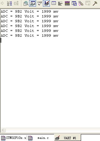
接下来在Peripheral菜单中选择USART1,打开串口仿真窗口。最后点击Debug工具条的运行按钮,即可在USART1仿真窗口中看到采集到的模拟电压值了。

在万利的EK-STM32开发板上运行时,只需选择Debug工具为“ST Link-II” ,然后将程序下载到开发板,用串口线将开发板上的USART1和电脑相连,即可在串口调试助手中收到模拟电压值了,旋转开发板上的电位器可以调节输入的模拟电压。
好了,今天很累了,先到这里,祝大家实验成功!
用户208051 2012-11-21 10:58
用户506238 2008-11-28 16:26
用户506238 2008-11-28 16:13
用户506238 2008-11-28 12:05
用户1560991 2008-7-23 15:30
用户158184 2008-7-22 15:42
用户1113894 2008-7-21 16:41
用户703457 2008-1-31 09:50
好东西!!!!!!!!!!!!!!!!!!!!!