

依据rh850的U2A为案例:
| # | File | Directory | Description |
| 1 | startup.850 | Project root/src/ | PE0/PE1 Startup Routine Call, 启动程序的调用向量表 |
| 2 | startup_PE0.850 | Project root/src/ | PE0 Startup Routine, Vector Table |
| 3 | startup_PE1.850 | Project root/src/ | PE1 Startup Routine, Vector Table |
| 4 | startup2.850(※1) | Project root/src/ | PE2/PE3 Startup Routine Call, Vector Table |
| 5 | startup_PE2.850(※1) | Project root/src/ | PE2 Startup Routine, Vector Table |
| 6 | startup_PE3.850(※1) | Project root/src/ | PE3 Startup Routine, Vector Table |
| 7 | main.c | Project root/src/ | Main Routine |
| 8 | main_pe0.c(※1) | Project root/src/ | PE0 Main Routine |
| 9 | main_pe1.c(※1) | Project root/src/ | PE1 Main Routine |
| 10 | main_pe2.c(※1) | Project root/src/ | PE2 Main Routine |
| 11 | main_pe3.c(※1) | Project root/src/ | PE3 Main Routine |
| 12 | section.ld(※1) | Project root/ | Section Settings |
PE 0,1,2,3 是内核PE0,PE1是内核;
PE2,PE3是锁步核;
“.850” 这里算瑞萨的向量文件;里面是汇编程序;
你熟悉下汇编的指令是可以看懂的,主要是程序启动后根据这些向量去指向映射的区域,你就这么理解。
“.c”这里是c语言的文件,我们写代码的区域;
“ld” 文件是链接脚本文件。
“gpg”文件是ghs的编译器生成文件文件;

| 1 | .cintvect | First of interrupt vector table of PE0/PE1 一个中断向量表 |
| 2 | .coldboot | Boot controller of PE0/PE1 开启控制 |
| 3 | .intvect_PE0 | Interrupt vector table of PE0 0内核的中断向量表 |
| 4 | .intvect_PE1 | Interrupt vector table of PE0 1内核的中断向量表 |
| 5 | .rozdata | Fixed data 固定的数据---这里理解是代码数据段 |
| 6 | .robase | |
| 7 | .rosdata | |
| 8 | .rodata | |
| 9 | .text | |
| 10 | .ascet_const | |
| 11 | .mytext0 | |
| 12 | .fixaddr | |
| 13 | .fixtype | |
| 14 | .secinfo | |
| 15 | .syscall | |
| 16 | .romdata | Data with initial value (ROM) 初始化ROM |
| 17 | .romsldata | |
| 18 | .cintvect2 | Reset vector table of PE2/PE3 复位向量表 |
| 19 | .coldboot2 | Boot controller of PE2/PE3 2/3内核的开启控制 |
| 20 | .intvect_PE2 | Interrupt vector table of PE2 2内核的中断向量表 |
| 21 | .intvect_PE3 | Interrupt vector table of PE3 3内核的中断向量表 |
| 22 | .romdata | Data with initial value (ROM) 初始化rom数据 |
| 23 | .data | Data with initial value (RAM) 初始化RAM数据 |
| 24 | .bss | Data without initial value (RAM) 没有初值的RAM数据 |
| 25 | .sdabase | SDA (Small Data Area) base register 数据区域寄存器 |
| 26 | .stack | Stack area 堆区域 |
| 27 | .heapbase | Base address of heap area 首数据的基础地址 |
| 28 | .heap | Heap area 首区域 |
这里对ld文件做简单介绍:脚本文件就是脚本指令组成的 我们解释下常见的脚本指令:
1、ENTRY(SYMBOL) : 将符号SYMBOL的值设置成入口地址。
入口地址(entry point): 进程执行的第一条用户空间的指令在进程地址空间的地址)
ld有多种方法设置进程入口地址, 按一下顺序: (编号越前, 优先级越高)
1, ld命令行的-e选项
2, 连接脚本的ENTRY(SYMBOL)命令
3, 如果定义了start 符号, 使用start符号值
4, 如果存在 .text section , 使用.text section的第一字节的位置值
5, 使用值0
1、ENTRY(SYMBOL) : 将符号SYMBOL的值设置成入口地址。
入口地址(entry point): 进程执行的第一条用户空间的指令在进程地址空间的地址)
ld有多种方法设置进程入口地址, 按一下顺序: (编号越前, 优先级越高)
1, ld命令行的-e选项
2, 连接脚本的ENTRY(SYMBOL)命令
3, 如果定义了start 符号, 使用start符号值
4, 如果存在 .text section , 使用.text section的第一字节的位置值
5, 使用值0
2 、INCLUDE filename : 包含其他名为filename的链接脚本
相当于c程序内的的#include指令, 用以包含另一个链接脚本.
脚本搜索路径由-L选项指定。 INCLUDE指令可以嵌套使用, 最大深度为10.
即: 文件1内INCLUDE文件2, 文件2内INCLUDE文件3… , 文件10内INCLUDE文件11. 那么文件11内不能再出现 INCLUDE指令了.
3 、INPUT(files): 将括号内的文件做为链接过程的输入文件
ld首先在当前目录下寻找该文件, 如果没找到, 则在由-L指定的搜索路径下搜索. file可以为 -lfile形式,就象命令行的-l选项一样.
如果该命令出现在暗含的脚本内, 则该命令内的file在链接过程中的顺序由该暗含的脚本在命令行内的顺序决定.
4 、GROUP(files) : 指定需要重复搜索符号定义的多个输入文件
file必须是库文件, 且file文件作为一组被ld重复扫描,直到不在有新的未定义的引用出现。
5 、OUTPUT(FILENAME) : 定义输出文件的名字
同ld的-o选项, 不过-o选项的优先级更高. 所以它可以用来定义默认的输出文件名. 如a.out
6 、SEARCH_DIR(PATH) :定义搜索路径,
同ld的-L选项, 不过由-L指定的路径要比它定义的优先被搜索。
7 、STARTUP(filename) : 指定filename为第一个输入文件
在链接过程中, 每个输入文件是有顺序的. 此命令设置文件filename为第一个输入文件。
8 、OUTPUT_FORMAT(BFDNAME) : 设置输出文件使用的BFD格式
同ld选项-o format BFDNAME, 不过ld选项优先级更高.
9 、OUTPUT_FORMAT(DEFAULT,BIG,LITTLE) : 定义三种输出文件的格式(大小端)
若有命令行选项-EB, 则使用第2个BFD格式; 若有命令行选项-EL,则使用第3个BFD格式.否则默认选第一个BFD格式.
TARGET(BFDNAME):设置输入文件的BFD格式
同ld选项-b BFDNAME. 若使用了TARGET命令, 但未使用OUTPUT_FORMAT命令, 则最用一个TARGET命令设置的BFD格式将被作为输出文件的BFD格式.
另外还有一些:
ASSERT(EXP, MESSAGE):如果EXP不为真,终止连接过程
EXTERN(SYMBOL SYMBOL ...):在输出文件中增加未定义的符号,如同连接器选项-u
FORCE_COMMON_ALLOCATION:为common symbol(通用符号)分配空间,即使用了-r连接选项也为其分配
NOCROSSREFS(SECTION SECTION ...):检查列出的输出section,如果发现他们之间有相互引用,则报错。
对于某些系统,特别是内存较紧张的嵌入式系统,某些section是不能同时存在内存中的,所以他们之间不能相互引用。
OUTPUT_ARCH(BFDARCH):设置输出文件的machine architecture(体系结构),BFDARCH为被BFD库使用的名字之一。可以用命令objdump -f查看。
可通过 man -S 1 ld查看ld的联机帮助, 里面也包括了对这些命令的介绍.
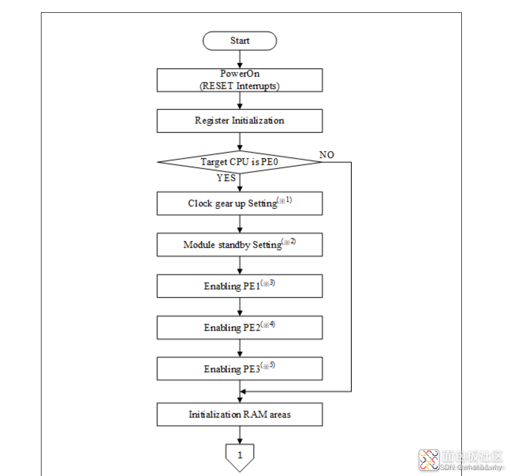
下面看下瑞萨的片子的启动过程其他单片机基本也是这个过程:(重点)


中断向量表--复位--内核进程启动--单内核进程运行--单内核进入进程等待-其他内核进程运行
| 1 | Power on (Reset interrupts) | - | startup.850 startup2.850 | The process of PE0 and PE1 are implemented in vector table of startup.850, the process of PE2 and PE3 are implemented in vector table of startup2.850. |
| 2 | Initializing registers | _RESET _RESET2 | startup.850 startup2.850 | The process of PE0 and PE1 are implemented in startup.850, the process of PE2 and PE3 are implemented in startup2.850. |
| 3 | Clock gearup settings | _clock_gearup | startup.850 | To be processed only when running PE is PE0. (※1) |
| 4 | Module standby settings | _module_standby_set | startup.850 | To be processed only when running PE is PE0. (※2) |
| 5 | Enabling PE1~3 | __start_PE0 | startup.850 | To be processed only when running PE is PE0. (※3) (※ 4) (※5) |
| 6 | Initializing RAM areas | __start_PE0 __start_PE1 __start_PE2 __start_PE3 | startup.850 startup2.850 | To be processed with “_hdwinit_PE0” when the running PE is PE0, with “_hdwinit_PE1” when the running PE is PE1, with “_hdwinit_PE2” when the running PE is PE2, and with “_hdwinit_PE3” when the running PE is PE3. |
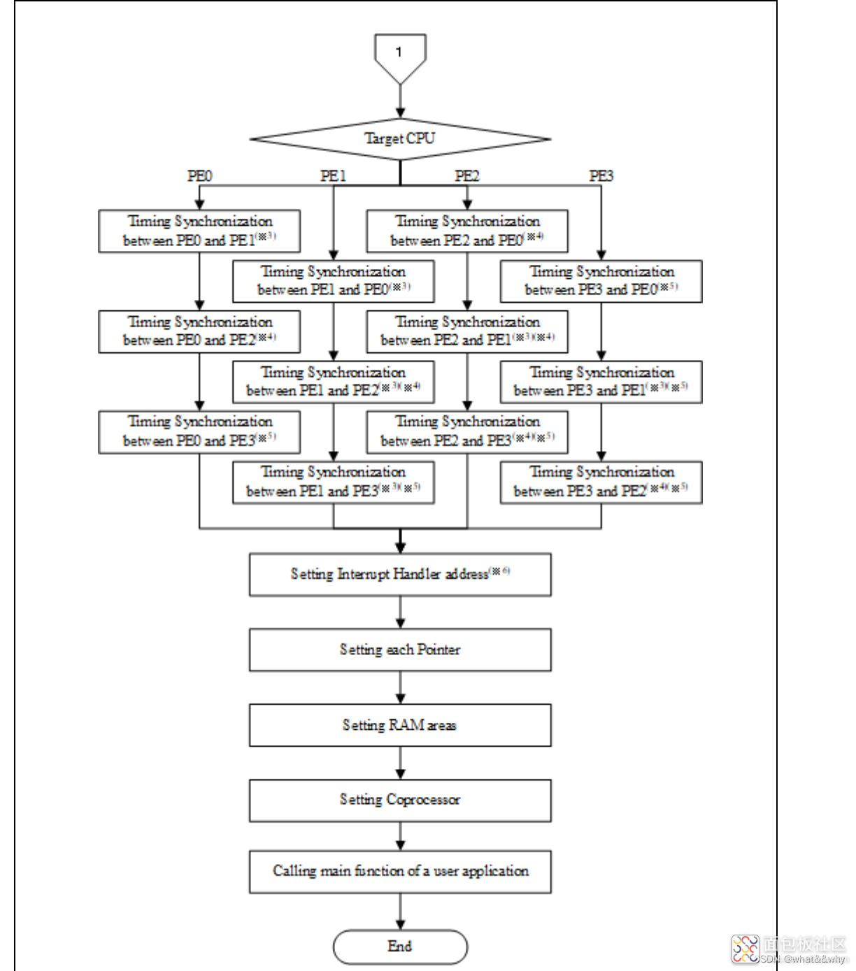
| 7 | Timing synchronization | __start_PE0 __start_PE1 __start_PE2 __start_PE3 | startup.850 startup2.850 | To be processed with “_hdwinit_PE0” when the running PE is PE0, with “_hdwinit_PE1” when the running PE is PE1, with “_hdwinit_PE2” when the running PE is PE2, and with “_hdwinit_PE3” when the running PE is PE3. (※3) (※4) (※5) |
| 8 | Interrupt handler address settings | _init_eiint _init_eiint2 | startup.850 startup2.850 | The process of PE0 and PE1 are implemented in startup.850, and the process of PE2 and PE3 are implemented in startup2.850. |
| 9 | Initializing each pointer | _RESET_PE0 _RESET_PE1 _RESET_PE2 _RESET_PE3 | startup_PE0.850 startup_PE1.850 startup_PE2.850 startup_PE3.850 | To be processed with “_RESET_PE0” when the running PE is PE0, with “_RESET_PE1” when the running PE is PE1, with “_RESET_PE2” when the running PE is PE2, and with “_RESET_PE3” when the running PE is PE3. (※3) (※4) (※5) |
| 10 | Setting Coprocessor | _RESET_PE0 _RESET_PE1 _RESET_PE2 _RESET_PE3 | startup_PE0.850 startup_PE1.850 startup_PE2.850 startup_PE3.850 | To be processed with “_RESET_PE0” when the running PE is PE0, with “_RESET_PE1” when the running PE is PE1, with “_RESET_PE2” when the running PE is PE2, and with “_RESET_PE3” when the running PE is PE3 |
| Calling a main function of user application | _RESET_PE0 _RESET_PE1 _RESET_PE2 _RESET_PE3 | startup_PE0.850 startup_PE1.850 startup_PE2.850 startup_PE3.850 | To be processed with “_RESET_PE0” when the running PE is PE0, with “_RESET_PE1” when the running PE is PE1, with “_RESET_PE2” when the running PE is PE2, and with “_RESET_PE3” when the running PE is PE3 |
下面是一个U2A的启动案例----重点
Power-On (RESET Interrupts)----电源开启--进入复位中断
Initializing Registers----初始化寄存器
Clock Gearup Settings----时钟开始设置
Module Standby Settings---使能等待模式
Enabling PE1~3----使能内核
Initializing RAM Areas----初始化RAM区域
Timing Synchronization---内核同步运行
Setting Interrupt Handler Address----设置中断首地址--标志位理解
Initializing Each Pointers----初始化堆指针
Setting Coprocessor---设置浮点--或者16位进制
Calling a Main Function of User Application---回调用户程序
下面是寄存器的案例 根据寄存器的解释看下流程:
| 一 | Program registers | r1~r31 | 0 | |
| 二 | Basic system registers | EIPC | 0 确认EI级别异常时,状态保存寄存器---EI状态 | |
| 3 | FEPC | 0 确认EF级别异常时,状态保存寄存器---EI状态 | ||
| 4 | CTPC | 0 CALLT执行状态保存寄存器 | ||
| 5 | EIWR | 0 EI级异常工作寄存器 读写异常 | ||
| 6 | FEWR | 0 EF级异常工作寄存器 读写异常 | ||
| 7 | EBASE | 0 异常处理程序向量地址 | ||
| 8 | INTBP | 0 中断处理程序“地址”表的基址 | ||
| 9 | MEA | 0 内存错误地址 | ||
| 10 | MEI | 0 内存错误信息 | ||
| 11 | RBIP | 0 寄存器库初始指针 | ||
| 12 | PSW | 0x00010020 状态字 | ID=1: Prohibit receiving EI level exceptions. CU0=1: Enable FPU | |
| 三 | FPU system registers | FPSR 浮点设置 | 0x00220000 | Value after Reset |
| 14 | FPEPC | 0 当确认FE级别异常时,状态保存寄存器 | ||
| 15 | FPST | 0 浮点运算状态 | ||
| 16 | FPCC | 0 浮点运算比较结果 | ||
| 四 | MPU function system registers | MCA | 0 | |
| 18 | MCS | 0 内存保护设置检查大小 | ||
| 19 | MCR | 0 内存保护设置检查结果 | ||
| 20 | MPLANote1 | 0 保护区最小地址 | ||
| 21 | MPUANote1 | 0保护区最大地址 | ||
| 22 | MPAT Note1 | 0 保护区属性 | ||
| 23 | MPID0 | 0 可以访问保护区域的SPID | ||
| 24 | MPID1 | 0 | ||
| 25 | MPID2 | 0 | ||
| 26 | MPID3 | 0 | ||
| 27 | MPID4 | 0 | ||
| 28 | MPID5 | 0 |
| 29 | MPU function system registers | MPID6 | 0 |
| 30 | MPID7 | 0 | |
| 31 | MCI 内存保护设置检查SPID | 0 | |
| 五 | Cache operation function registers | ICTAGL | 0 |
| 33 | ICTAGH 指令缓存标签Hi访问 | 0 | |
| 34 | ICDATL 指令缓存标签Li访问 | 0 | |
| 35 | ICDATH 指令缓存数据Hi访问 | 0 | |
| 36 | ICERR 指令缓存错误 | 0 | |
| 六 | Virtualization support function system register | HVSB | 0 |
| 38 | Guest Context Register 当虚拟化支持函数有效时 这些必须设置为0 | GMEIPC | 0 |
| 39 | GMFEPC | 0 | |
| 40 | GMFEPSW | 0 | |
| 41 | GMEIIC | 0 | |
| 42 | GMFEIC | 0 | |
| 43 | GMEBASE | 0 | |
| 44 | GMINTBP | 0 | |
| 45 | GMEIWR | 0 | |
| 46 | GMFEWR | 0 |
| GMEIPC, GMFEPC, GMEBASE, GMINTBP, GMEIWR, GMFEWR, GMMEA, GMMEI.----------------设置为0 |
作者: 用户3884983, 来源:面包板社区
链接: https://mbb.eet-china.com/blog/uid-me-3884983.html
版权声明:本文为博主原创,未经本人允许,禁止转载!
 /2
/2 
文章评论(0条评论)
登录后参与讨论