

High speed signals transmitted along PCB tracks tend to suffer from high frequency attenuation, which makes it difficult for the receiver to interpret the information. The effect is similar to a low pass filter which decreases the gain of the high frequency signal. The main culprits are dielectric loss and skin effect, although crosstalk and stub reflections caused by poor termination can also cause issues. Please refer to the last article for the fundamentals of dielectric loss and skin effect.
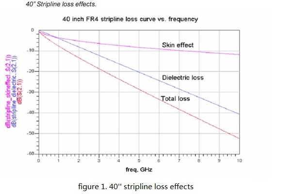
As frequency increases, dielectric loss is the dominant factor in high frequency attenuation, since its effect is proportional to frequency, whereas skin effect is proportional to the square root of frequency. Figure 1 shows the strip line loss effects against frequency.

A further complication is caused by dispersion, where the losses in the medium cause the different frequency components of the signal to have different delays as they travel along the transmission line. This further reduces signal amplitude, and adds residual error from previous bit leading to increased inter symbol interference. We can ignore the impact of dispersion since the attenuation is the leading factor. Furthermore, on the FR4 board, the dispersion is nearly disappeared at 10 MHz and above.
So, the high frequency attenuation is what we are facing. The Pre-emphasis and Equalization are the methods can be employed to resolve it.
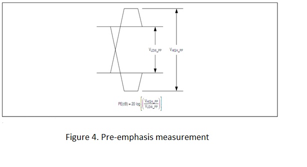
The solution is to provide a method of boosting purely the high frequency components of the signal, while leaving the low frequency components in their original state. One way to achieve this is to use pre emphasis. Pre-emphasis operates by boosting the high frequency energy every time there is a transition in the data, since this is when the most issues occur. The pre-emphasis circuitry works by comparing the previously transmitted data bit with the current data bit. If the two bits are the same level, then the current bit is transmitted at the normal level. If the two bits are different, then the current bit is transmitted at a higher magnitude. Figure 2 demonstrates the circuitry.

When the speed of the lane exceeded a level, such as 5Gbps or above, the Far-end eye-diagram tends to difficult to be improved only by Pre-emphasis. In this case, what should be brought into play is equalization. Equalizer acts as a high pass filter and amplifier. This allows the receiver to rebuilt the signal and capture the contents correctly.
By applying equalization, the low frequency components are attenuated. This equalizes the frequency response so that the delta between the low frequency and high frequency components are reduced, which minimizes the ISI effects from the transmission medium.
Dispersion can also be overcome within the equalizer which can be designed to cut off the unwanted frequency components, thus stopping them from spreading into the next symbol.
Aim to minimize the transmission system’s BER, the Pre-emphasis and Equalization should be balanced to obtain the best result. Overweighed pre-emphasis amplified the high frequency noise; this will increase the cross-talk and bring side effects to the receiver. If we towards to equalization too much, the power consumption of the receiver will be rise rapidly, especially on a die which owns dozens of SERDES. And the Testability of the Equalization is not as good as the Pre-emphasis since it cannot be test by oscilloscope directly. So, on a long distance multichannel system with high integration level, the Pre-emphasis and Equalization should be balanced.
 /5
/5 
用户1277994 2010-11-6 07:18