

UC3-L0 Xplained 使用记录
June 18, 2011 by Jevon
1. 下载相关官方开放文档;
关于UC3-L0 Xplianed 的两个文档,在官网都能找到;
UC3-L0 Xplianed Hardware use guide.pdf
UC3-L0-Xplianed startd guide.pdf
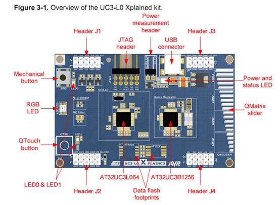
整体认识开发套件:


注意上图中的 Power measurement header 其是用来测量功耗的, 上电前确保其用短路帽跳好或者用电流表接通,否则会有烧毁芯片的可能;
2. 下载 该kit的usb 转串口的的驱动
XPLAINED_Virtual_Com_Port.inf (官网可以找到)
插上usb电源,安装好驱动,将在电脑的串口设备中有相应的设备串口号出现;
3. 开始体验预装demo;
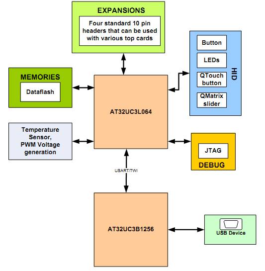
该开放套件预装的UC2-L0 Xplained demo 程序,上电后就可以来体验一下触摸按键的感觉了;这个DEMO包含了触摸按键,pwm调节led亮度,uart的通信;
下面是其演示功能的介绍来自官方文档:
The preprogrammed firmware in the AT32UC3L064 is a demonstration of the Atmel
QTouch? button and Atmel QMatrix slider. By pushing the QTouch button (QTB0),
LED1 will light up. The QTouch button will cycle through the selection of the colors
red, green, and blue for the RGB LED. When moving a finger on the QMatrix slider
(QMSlider), the intensity of the color selected by the QTouch button will change. The
RGB colors are controlled with 8-bit resolution PWM, which theoretically gives the
user the ability to mix up to 16.7 million colors.
6.1.1.1 Capacitive touch module
The preprogrammed firmware was made to demonstrate the built-in hardware
functionality of the AT32UC3L064 device. The device has a capacitive touch (CAT)
module, which can be used for both QTouch and QMatrix sensors. To demonstrate
this, the UC3-L0 Xplained board has one of each sensor; one QTouch button and one
QMatrix slider.
The design of the sensor defines if it is a QTouch or a QMatrix sensor. One of each is
included for demonstration. The QMatrix slider can also be used as four separate
QMatrix buttons.
The preprogrammed firmware uses the QTouch button to select among the three
colors of the RGB LED to control with the QMatrix slider. When touching the QTouch
button, LED1 will also light up while a touch is registered.
The QMatrix slider has an 8-bit resolution, which gives 256 different values according
to where on the slider the touch is held. This value is passed on to the PWM module,
which will set the brightness of the selected color on the RGB LED.
NOTE Register and accept the license to get access to the QTouch libraries included in the
source zip file provided with this application note.
6.1.1.2 Pulse width modulation controller
The AT32UC3L064 device has a pulse width modulation controller (PWMA), which
can output an 8-bit PWM signal on any of the I/O pins of the device. This module is
used to control the brightness of each of the colors on the kit’s RGB LED with the
value received from the QMatrix slider and the color selected by the QTouch button.
6.1.1.3 UART
The preprogrammed firmware has a UART module set up for transferring serial data
through the board controller to a PC. This can be used for sending data to the PC to
implement any communication in a custom design. This gateway is currently used to
send data from the QTouch driver to the PC, making it possible to reprogram the
board controller with QTouch HID firmware and then use this to connect the board in
QTouch Studio for debugging and logging of QTouch data. The QTouch HID firmware
can be downloaded from ASF 2.2.x.
4. 下载安装FLIP 3.4.2 或者更高版本(下载包含有jav的版本),使用FLIP中的batchisp
命令行与板子的bootloader通信来下载程序;
下面是详细步骤:
5.1.2 Step-by-step guide
To program the device, follow these steps:
1. Disconnect the USB cable from the kit.
2. Press and hold the button (SW0) while re-attaching the USB cable.
3. Open the device manager and locate the COM port used by the kit:
4. Run the command below with the correct COM port:
Batchisp -device AT32UC3L064
-hardware RS232
-port COM19
-baudrate 115200
–operation onfail abort
memory flash
erase f
blankcheck
loadbuffer your_firmware_file.hex
program verify
start reset 0
5. AVR-STUDIO5.0 来下载调试程序
下载安装avr studio 5.0 并且安装 微软的 API 3.0加速;
把JTAGICE3连接到开发板的JTAG,并且上电开发板即可;可以用Tool 菜单中的
avr program进行flash的烧写等,也可以进行在线仿真;具体参考AVR STUDIO 5.0\
使用;
 /5
/5 
文章评论(0条评论)
登录后参与讨论