参考时钟:
一路差分时钟或者两路单端时钟
支持CMOS,LVPEL,LVDS参考电平,最高频率250MHz
晶体参考时钟16.62M--33.3M
输出时钟:
12路800MHz LVDS时钟输出,可分为四组,每组有分频器和相位延迟器。每个LVDS可以配置成两路CMOS时钟,频率小于250MHz
存储:
片上EEPROM via SPI and I2C
VCO/VCXO接口
LF: connet internally to the VCO control voltage node
BYPASS: bypass LDO
LD: Lock Detect, this pin has multiple selectable output
CP: charge pump. this pin cannects to an external loop filter.
REF2: the differential input for the PLL reference
REF1: the the differential input for the PLL reference
VCO divider input clk <2.4G
Channel divider input clk <1.6G
PLL:
参考时钟:0 - 250MHz (REFIN)LVDS crystal scillator 16.67 -- 33.3MHz
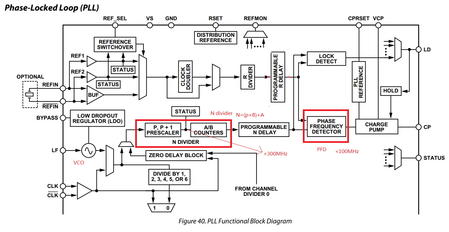
片上含有PLL,PLL可以使用片上的VCO或者外接VCO。PLL利用外部时钟产生精度更高的时钟,用于分频或者时钟分配,PLL时钟信号可以消除抖动和相位噪声。
PFD:监控两路输入信号的频率和相位的关系,然后控制CP充电或者放电。CP电流转换成电压驱动内部VCO的LF(或者外部VCO的调节点tuning node)控制频率调大或者调小。PFD监控的两路信号分别来自R分频器和N分频器,R时钟来自PLL的参考输入,N时钟来自于VCO
CP可以设置为高阻(holdover operation),正常模式(lock the PLL) 或者充电和放电(test mode)。CP电流大小可由编程控制0.6mA--4.8mA,分为八个梯度。
VCO输出时钟频率1400MHz -- 1800MHz
REFIN 控制寄存器0X01C
REFIN使用单端时钟时,0x18[7]设置为1,可以避免输入buffer调频
DLD Digital Lock Detect。 lock detect window time depends on CPRSET resister and three settings: the digital lock detect window bit (0x018[4]), the antibacklash pulse width
bit (0x017[1:0], ), and the lock detect counter (0x018[6:5]).
Holdover: 设置charge pump为高阻状态来实现holdover。
作用:当参考时钟缺失时,VCO可以保值一固定的频率,
手动Holdover使用SYNCpin ,边沿灵敏非电平灵敏
自动Holdover:保持在参考时钟消失前的频率
Holdover检测LD的电平,LD可以来自DLD,ALD或者CSDLD,0X01D[3]设置LD comparator
Zero Delay operation
by feeding the output of Channel 0 back to PLL N Register 0x01e[2:1]=01b
SP1=H,SP0=H ->SPI otherwise I2C, 地址由SP1和SP0状态决定


 /4
/4 
文章评论(0条评论)
登录后参与讨论