
一、写在前面... 1<?xml:namespace prefix = o ns = "urn:schemas-microsoft-com:office:office" />
Cuter今天看到匠人的《匠人手记之PIC》快速入门部分,提到ICD2与目标板、PC如何连接及其各自的上电顺序,原文为:“在应用的过程中,ICD2 的连接总是失败,报错也是千奇百怪。匠人潜心研究,得出正确的连接顺序。这个顺序虽然繁琐,但是可以取保连接成功。”有了点小小的想法——经过这几天的对PIC单片机的学习,Cuter发现掌握许多芯片和开发平台的捷径之一是认真阅读相关Datasheet和User guide。
就上述问题(ICD2连接顺序)而言,在Mplab IDE的Release Notes中有详细的说明,ICD2的用户手册中也有说明。摘录Release Notes相关原文如下:
8 Setting Up the MPLAB ICD 2 and Target Board
Note: The ICD headers need to be connected to a target board or else they may receive the ICD00083 debug error.
8.1 Powering the Target Board from the MPLAB ICD 2
1. Power the MPLAB ICD 2. DO NOT power the target.
2. Start MPLAB IDE.
3. Under the Debugger menu of MPLAB IDE, click "Connect".
4. After establishing communications with the MPLAB ICD 2, select Debugger>Settings.
5. In the Settings dialog, click the Power tab and ensure that the check box for "Power target circuit from MPLAB ICD 2" is checked. Click OK.
6. Now you should be able to erase and program components with the MPLAB ICD 2.
8.2 Powering the Target Board from its own power supply
1. Power the MPLAB ICD 2. DO NOT power the target.
2. Start MPLAB IDE.
3. Under the Debugger menu of MPLAB IDE, click "Connect".
4. After establishing communications with the MPLAB ICD 2, select Debugger>Settings.
5. In the Settings dialog, click the Power tab and ensure that the check box for "Power target circuit from MPLAB ICD 2" is NOT checked. Click OK.
6. Power the target system and then select Debugger>Connect.
7. Now you should be able to erase and program components with the MPLAB ICD 2.
由上可知,目标板的供电方式不同,各模块的连接和上电顺序是有区别的,自己摸索的话会费很大劲,相反地,很好地阅读数据手册和用户手册会避免很多类似问题。
想要很好的了解芯片资源,无疑是要阅读Datasheet的,Cuter感觉Microchip在Datasheet方便做的还是不错的,此处不说了,把Data Sheet抄过来也没啥意思!
2、 开发环境:MPLAB IDE V8.36
官方的开发环境,不用也没什么好办法。
l 对于初学者来说,用汇编语言编写程序有助于理解芯片结构及其资源,因此cuter 先学习用汇编语言编写程序,因此暂用MPLAB 自带的汇编语言编译器:MPASM? Assembler v5.33
l MPLAB IDE V8.36还集成了C语言编译器PICC V 9.65,Cuter打算熟练掌握汇编语言再开始C语言开发的学习
4、 硬件调试及编程工具:PROTEUS&MPLAB ICD 2
由于项目中要用PIC单片机,导师买了这套开发套件,用起来感觉还可以。事实上,Cuter一般是在PC上用Proteus进行仿真后,再用硬件仿真,多少可以少折磨芯片几次吧!
Datasheet中很多模块都有讲到模块的工作流程,按照工作流程编写程序便可得到最简单的测试程序
http://ww1.microchip.com/downloads/en/DeviceDoc/30292c.pdf
http://ww1.microchip.com/downloads/en/DeviceDoc/33023a.pdf
点亮一个LED:
;-----------------------------------
;利用EQU指令为一些寄存器和变量命名,
;以方便程序的编写
;-----------------------------------
STATUS EQU 0x03
RP0 EQU 0x05
TRISC EQU 0x87
PORTC EQU 0x07
LED0 EQU 0x00
org 000h ;设置主程序起始地址
Main
Nop ;空指令:ICD2调试的必须指令
bsf STATUS,RP0 ;将STATUS第5bit置1,选择bank1,因为TRISC,位于bank1
bcf TRISC,LED0 ;将端口C的第0位清0,设置该位为输出
bcf STATUS,RP0 ;将STATUS第5bit置0,选择bank0
bsf PORTC,LED0 ;将端口C的第0位置1,点亮LED0
goto $-1 ;跳转到距离当前语句距离为-1的语句,即上一条语句
END ;程序结束(不可或缺)
Proteus仿真图如下:
<?xml:namespace prefix = v ns = "urn:schemas-microsoft-com:vml" />
不要小瞧这个如此简单的程序,处理复杂问题最好的办法就是化繁为简,程序简单减少了程序调试工作带来的错误和警告,使Cuter对PIC学习有了小小的自信并且顺利完成下述目标:
1. 熟悉开发环境MPLAB
如何建立一个新项目、添加源文件、选择语言工具。
2. 学习程序调试
如何进行编译、连接、除错(警告),如何debug,熟悉仿真软件Proteus的使用,以及如何根据自己的需要查看变量、寄存器、I/O口的数据。
3. 学习ICD2的使用
如何完成PC、ICD2和目标板的连接,如何利用ICD2调试程序,如何利用ICD2烧写程序。
至此,算是完成入门了或是说找到入门之道了!
题外话:
事实上,Cuter在调试这个最最最……简单的程序时,刚开始没有对程序进行格式化,就碰到一堆警告:
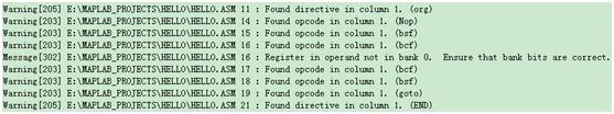
Found opcode in column 1?难道操作码不能顶行写,必须要有缩进?试一下,将代码格式化之后,发现所有警告消失,Done!“不就是警告吗?有什么大不了!”Cuter觉得要想不湿鞋的话就不要常走河边,谁知道会有什么意外?
由此可知,由于存在太多的未知,入门程序还是越简单越好啊!


 /5
/5 


文章评论(0条评论)
登录后参与讨论