

In my previous blog, I gave an overview of what the PICAXE system comprises and an account of my first forays into programming the beast. As I noted, I wanted to go a bit further into the capabilities of the development environment and the PICAXE processor.
In Part 1, I referred to the naming restrictions on variables and input/output ports. To make your programs easier to understand, you can use the "SYMBOL" command to give a less cryptic name to any of these. For example:

This statement associates the name "DELAY" with byte variable "b0." Once you've made this association, you can use statements like the following:

You can do the same type of thing with port names for the inputs and outputs.
The programming editor contains a "SIMULATE" function, which enables you to single-step through a program and see what the outputs would do. I tried it on my counter program and it worked fine, opening a new window with a picture of the chip, showing the LED pins going on and off as the program stepped through the statements. You don't need to be plugged into a board to do this—it's an offline simulator.
My next task was to start using the analogue-to-digital converter (ADC). PICAXE processors contain 10bit ADCs. I thought that using this feature would entail some setup and configuration, but not so! There is a "READADC (port)" command that sets up the specified port for ADC use, reads the ADC on the specified port, and presents the eight most significant bits for use (if you wish to access the full 10 bits, you can use the "READADC10" command). As I was using a small PICAXE that can only display three or four bits on LEDs, I wondered if I could use the three LEDs on my board to display the most-significant three bits of the 8bit value. My board has an LDR (light-dependent resistor) on one ADC port to give a convenient way of getting a variable voltage on that pin. To see if this was working properly I used the debug function. You just insert the "DEBUG" statement into your program, run it, open the debug function in the editor, and you can see the values of all variables. So I wrote a small program as follows:

When I ran this program and opened the debug window, I could see the value of the ADC output as variable "b0." Happily, with the ambient light in my office, this was around 125-126. If I covered the LDR with my finger it would go down to almost 0; if I shone a torch (flashlight) on it, it went up to around 240. So I knew I was reading the input value OK. Now, you can access the bit values of variable "b0" using the variables "bit0" to "bit7." Thus it was easy to access the most-significant three bits and use them to drive the LEDs as follows:

Wow! I had my 3bit ADC working! This whole process was absurdly easy and took far less time to actually do than it did to write about it here.
The next thing I decided to experiment with was some PWM (pulse-width modulation). The PICAXE has a "PWMOUT" command in the following form:
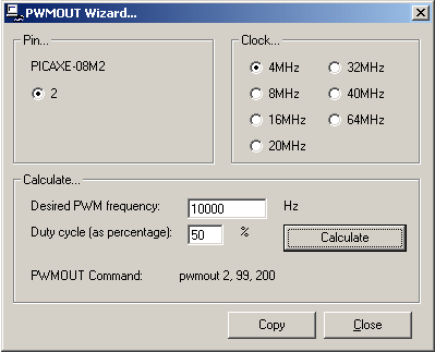
In this case, "period" is a variable in milliseconds from 0-255, while "duty cycle" is a value from 0 to 1023. You can use "period" to set the frequency (1/period) if that's important, and then a "duty cycle" of 100% is roughly 4x the "period" value. Don't worry if this sounds complicated because the editor has a Wizard to work everything out for you:

This Wizard helpfully gives you the command to use at the bottom, and you can also copy the command and paste it into your program. I had fun making the LED on output 2 (my only PWM output on this chip) "breathe" (gradually fade up and down). Again, the PICAXE makes all this really easy and the command reference is detailed and easy to follow.
David Ashton
Jack of All Trades
 /1
/1 
文章评论(0条评论)
登录后参与讨论