

One of the EE Times editor, the illustrious Max Maxfield, is currently on a quest to learn the Arduino. In one of his recent blogs, Max said the following:
My most recent fling was playing with a PICAXE controller board based on a Microchip PIC; I programmed it using a form of BASIC. The PICAXE was a lot of fun, but it's too low-level for what I need.
This gave me some cause for concern, as I had coincidentally just ordered a small PICAXE kit as part of a special offer by one of my suppliers. I raised this as a comment in Max's column, wondering if I'd done the right thing. In response, Max went to some lengths to justify his own interest in the Arduino, but he also said: "...for just messing around with your own projects, I think you will love the PICAXE."
Before we proceed further, let me give you a little background. I did a bit of microprocessor programming in the "good old days"—the 80s and 90s—mostly on the 8080 and the Z80. My life then shifted more into telecom, where I work to this day. But modern telecom has grown increasingly divorced from the electronics that supports it, and I have felt a strong desire to get back to the electronics side of things. My recent programming has been mainly on things like PABXs and Procomm at work, so I took the bull by the horns and ordered the PICAXE kit.
I have done a lot with BASIC in the past, including the old Sinclair ZX81 and Spectrum, and I also programmed a terminal emulator in Qbasic. The end result is that I got pretty good at BASIC, so I thought the PICAXE would be a good starting point for my foray into microcontrollers. I'd also like to learn C at some stage, but for the moment I wanted something I could get to grips with quickly for a few ideas I wish to "mess around with," as Max puts it.
On top of everything else, Max then asked me if I would write a couple of blogs on my experiences with the PICAXE system. Having Max nipping at your heels for blogs to post is a fine incentive to get going and do something, so I jumped at the chance.
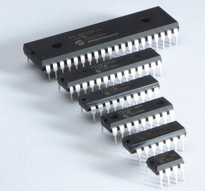
The PICAXE world consists of various Microchip MCUs that have been pre-programmed with a bootstrap loader that enables very easy programming without an expensive programmer. These are coupled with a development environment that lets you write programs in a variation of the BASIC language. The available chips range from the 08M2, which has 8 pins and 6 I/O lines, to the 40X2, which has 40 pins and 33 I/0 lines.
Programming (on PICAXE's own boards) is performed through a 3.5 mm stereo type jack connector like those used on MP3 players. All the chips offer analogue-to-digital converters (ADCs), pulse width modulation (PWM), I2C and serial connections, and touch interfaces, as well as standard digital I/O. The larger ones also offer SPI and a couple of other options. This is all pretty tasty to someone whose last hands-on experience was with systems that needed vast arrays of chips to achieve all the above, though I have kept a hands-off eye on microcontroller technology and pretty much knew what to expect.
Memory-wise, the PICAXE chips offer fairly limited capacities compared to the huge memories available in other MCUs. To be fair, however, these devices are aimed more at the educational and hobby/DIY market than professional applications (click here to see a table detailing the capacities and capabilities of the various PICAXE chips.

Apart from bare chips, PICAXE offers various DIY kits and boards to get you started. There is a huge array of gear available, including add-on sensor boards and output devices. For instance, you can get various LCD output modules that only require a one-pin serial connection to the PICAXE.
There are various boards oriented towards specific tasks. The 28X2 PICAXE comes as a 0.3" 28-pin chip, but you can get a 0.6" board containing the 28X2 MCU, download socket, voltage regulator, and reset button that would be ideal for using on a breadboard. You can also get a 28X2 "Shield Base" board, which is compatible with Arduino Shields for expansion. All in all, there's some very tasty stuff indeed (click here to see an index of boards, chips, and kits—use the small blue links under the "Product Codes" to get more information).
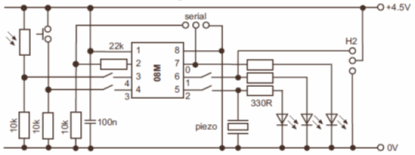
Back to my little kit. I got one of the smaller versions—the AXE092 kit with the smallest 08M2 chip; three LEDs and a piezo sounder for output; and a switch and an LDR (light-dependent resistor) to provide digital and analogue inputs. The assembly was very easy, thanks to the excellent instructions, and it would be even for someone with little electronics experience. Power is from a small 3xAA battery box (4.5V), though you could also use a 3-5V power supply. My kit's programming lead was serial (there is a USB version now, which is probably why my kit was so cheap!) But you can make up your own serial lead if you wish. Here is a schematic of my kit:

Observe that the schematic refers to the chip as an 08M, which is an older chip; mine came with the latest 08M2. The programming pins are 2 (Rx) and 7 (Tx). As you can see, Pin 7 (= port 0) is also used as a digital output. You can use the programming input, Pin 2 (= port 5, not shown above) for other purposes, but you then have to reset the chip (or use the BASIC DISCONNECT command) before programming it again. The AXE092 kit does not appear in the list I mentioned above—I think it's been discontinued (again, this is probably why I got it so cheap), but there is a small User Manual available.
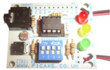
A photo of the AXE092 board is shown below (note that this photo was taken from the manual—the LEDs on the board I built stand up straight and my resistors are all oriented the same way, LOL):

The AXE092 PICAXE Kit. The big black thing at the upper left is the programming socket. The small black thing at the lower left is a push switch. The DIP switch is for disconnecting outputs to use them for other things. The upper wires on the right-hand side go to the battery; wires on the lower right-hand side go to a piezo sounder.
It was at this point that I ran into my first problem—I found my PC did not have a serial port. The Device Manager said that I did, but I could not find "hide or hair" of it. My motherboard manual also said I had such a port, but I discovered that was for a previous board version. Fortunately, I had a USB-to-Serial adapter knocking around, so I got that out.
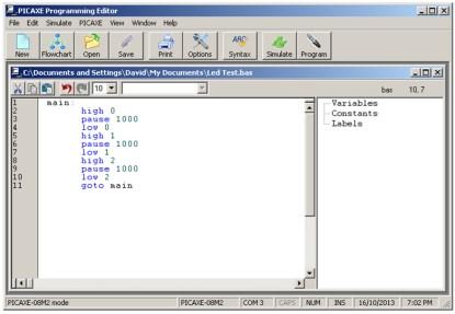
I had previously installed the software that came on a CD with my kit. This installed the "PICAXE Programming Editor," the manuals, which I didn't look at much (it's a guy thing), and a driver for the USB programming cable (which I didn't have). Installation was quick and easy. The screen is simple and fairly intuitive and there are large icons for the common tasks as illustrated below:

In my case, I had to change the COM port from COM1 to COM3—using the "Options" tab—for my USB-to-serial lead. I then entered—from memory—a program that was on the instruction sheet for my kit, whose purpose is to make the three LEDs flash in sequence. Here's that program:
The first time I tried to download the program to the board, I was presented with an error message telling me that the wrong hardware was connected—the environment was set up for a 20M2 chip and it had found an 08M2. I corrected this (the error message helpfully took me to the "Options" screen to do this) and I tried again. This time I got another error message telling me that Pin C.3 was input only. My port numbers should have been 0, 1, and 2, not 1, 2, and 3 (d'oh!). This was also quickly corrected and my little board was soon flashing its three LEDs in sequence. Observant readers may have noticed that the correct program (without comments) is in the screenshot above.
I quickly tried a few other things. I had earlier skimmed through the tutorials and recalled that there was a "SOUND" command that made tones. The editor, through the "Help" tab, offers easy access to the manuals. These are in three parts: "Getting Started," which offers a wealth of general information on how microcontrollers work, and more specific information on the PICAXE Chips and system; "Basic Commands," which—as you might expect—provides a command reference; and "Interfacing Circuits," which has some basic electronic circuits for inputting to and outputting from your PICAXE pins.
A few seconds later, having consulted the command reference for the "SOUND" command, I had a loop program going making a rising tone. I then tried making a 3bit binary counter using nested FOR...NEXT loops. I cut and pasted a bit here and got distracted and did not notice that my last "NEXT" statement referred to B0 instead of B2. When I tried to download the program, the error message told me specifically that B0 should be B2. Probably not the hardest thing to deduce, but I was impressed at how helpful the error messages were whenever I did anything wrong—this is a big plus for anyone starting out.
With my previous experience with BASIC, I found the programming very easy. I did have to refer to the manuals a bit, but mostly for commands and naming conventions. For instance, variables will be named "bitx," "bx," or "wx" depending on whether they are bit variables, byte variables, or (16bit) word variables. Also, these variable overlap in memory; for example, 'bit0' through 'bit7' are the same as byte 'b0,' so you have to keep your wits about you there. On the plus side, this can be extremely useful if you want to extract bits from a byte. To read a digital input, you use the "PINx" statement, where 'x' refers not to the actual pin number but to the port number. Meanwhile, outputting digital values—as shown in my program above—uses "HIGH x" or "LOW x." Some of this is a bit tricky at first, but really—as compared to the GWBASIC and QuickBasic that I was used to—it's just a matter of getting used to some new commands and inputting and outputting using pins and ports instead of keyboard and screen. So, not too much of a learning curve at all.
Max was right. I am having a lot of fun. I can already see the limitations of the PICAXE system, but that is looking from the viewpoint of professional applications. For the kind of stuff I get up to in my workshop, the PICAXE platforms are pretty much ideal. I am already thinking about more programming—using the ADC for example—and using some of the finer features of the programming environment, and getting a bigger PICAXE chip to play with, and... But my bed is calling, so I'll leave all that for another day and—if Max will let me—another blog.
David Ashton
Jack of All Trades
 /7
/7 
文章评论(0条评论)
登录后参与讨论