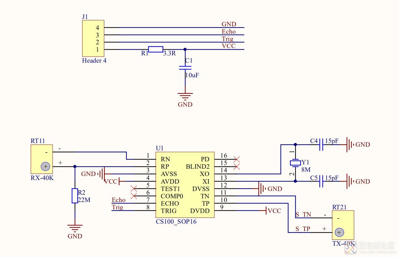
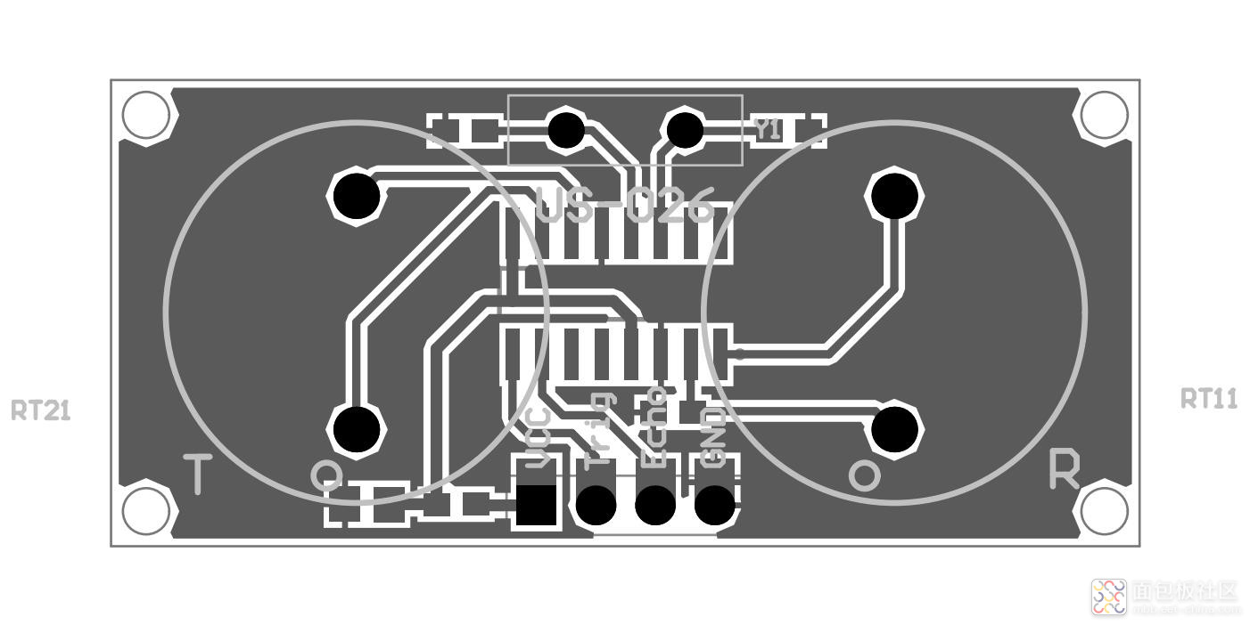
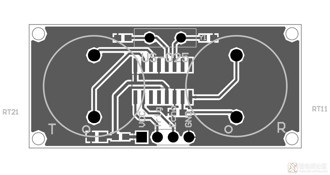
模块电原理图
测距工作原理 US-025/US-026 测距时序图
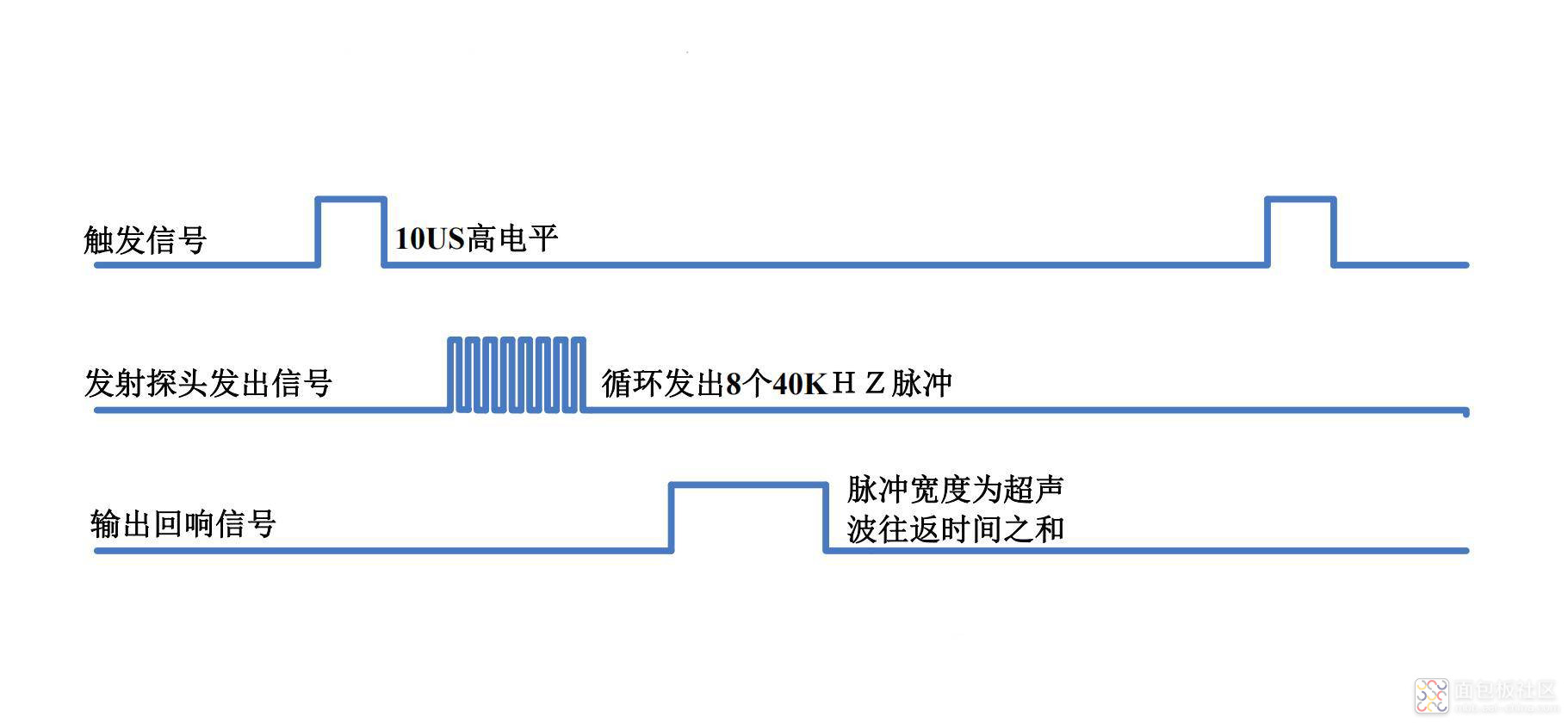
只需要在 Trig 管脚输入一个 10US 以上的高电平,系统便可发出 8 个 40KHZ 的超声波脉冲,然后检测回波信号。当检测到回波信号后,通过 Echo 管脚输出。根据 Echo 管脚输出高电平的持续时间可以计算距离值。即距离值为:(高电平时间*340m/s)/2。
超过测量范围时返回值及测量周期 当测量距离超过 US-025/US-026 的测量范围时,仍会通过Echo 管脚输出高电平的信号,高电平的宽度约为 66ms。
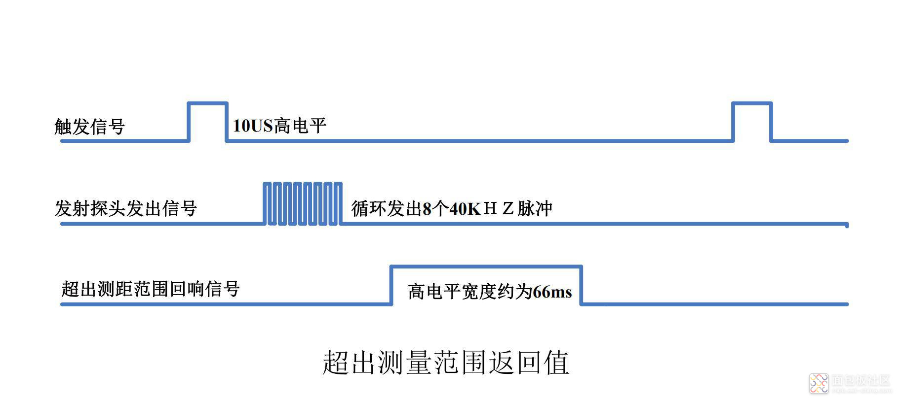
测量周期:当接收到 US-025/US-026 通过 Echo 管脚输出的高电平脉冲后,便可进行下一次测量,所以测量周期取决于测量距离,当距离被测物体很近时,Echo 返回的脉冲宽度较窄,测量周期就很短;当距离被测物体比较远时,Echo 返回的脉冲宽度较宽,测量周期也就相应的变长。最坏情况下,被测物体超出超声波模块的测量范围,此时返回的脉冲宽度最长,约为 66ms,所以最坏情况下的测量周期稍大于 66ms 即可(取 70ms 足够)。
接口说明
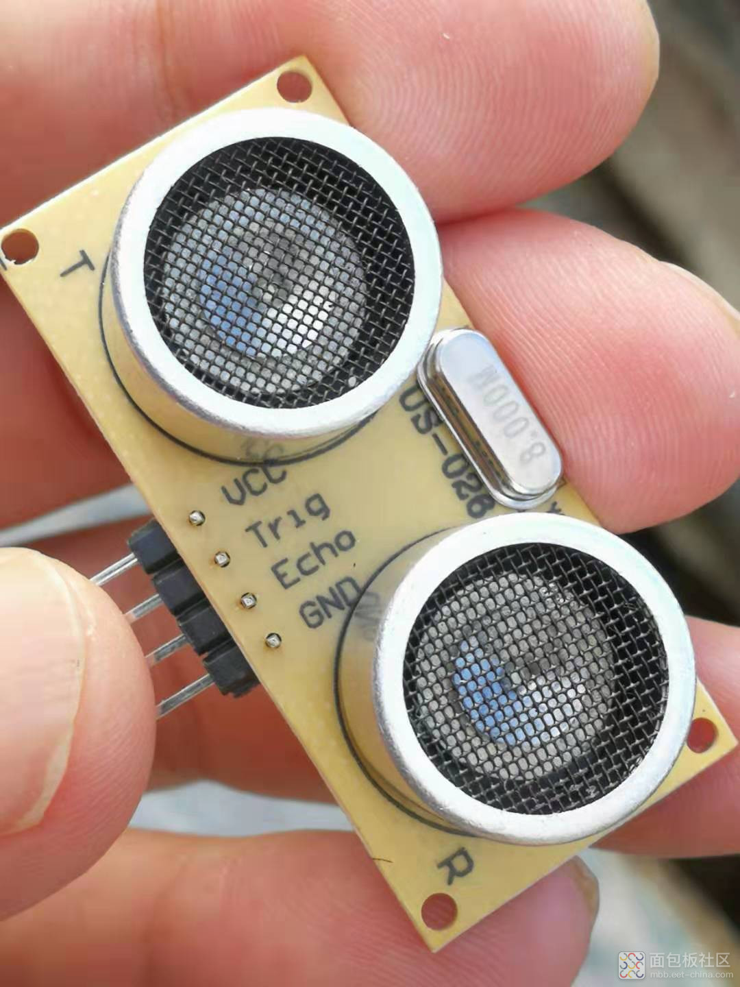
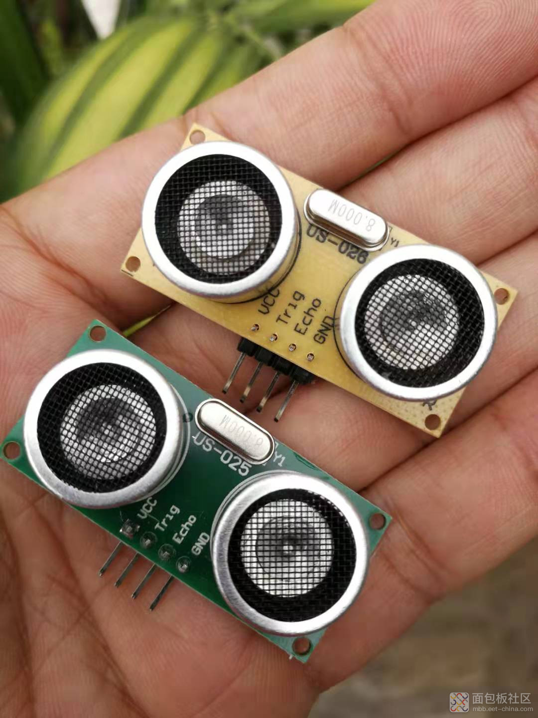
模块有一个接口:4 Pin 供电及通信接口,US-025 与US-026 接口相同。 4 Pin 接口为 2.54mm 间距的弯排针,如图 所示: 4 Pin 接口从左到右依次编号 1,2,3,4。它们的定义如下:
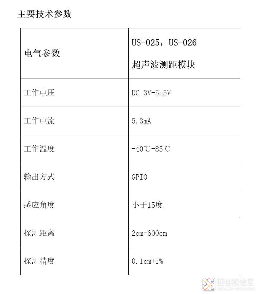
⚫ 1 号 Pin:接 VCC 电源(直流 3V-5.5V)。
⚫ 2 号 Pin:接外部电路的 Trig 端,向此管脚输入一个
10uS 以上的高电平,可触发模块测距。触发信号 10US高电平 发射探头发出信号 输出回响信号 循环发出8个40KHZ脉冲 脉冲宽度为超声 波往返时间之和
⚫ 3 号 Pin:接外部电路的 Echo 端,当测距结束时,此管脚会输出一个高电平,电平宽度为超声波往返时间之和。
⚫ 4 号 Pin:接外部电路的地。 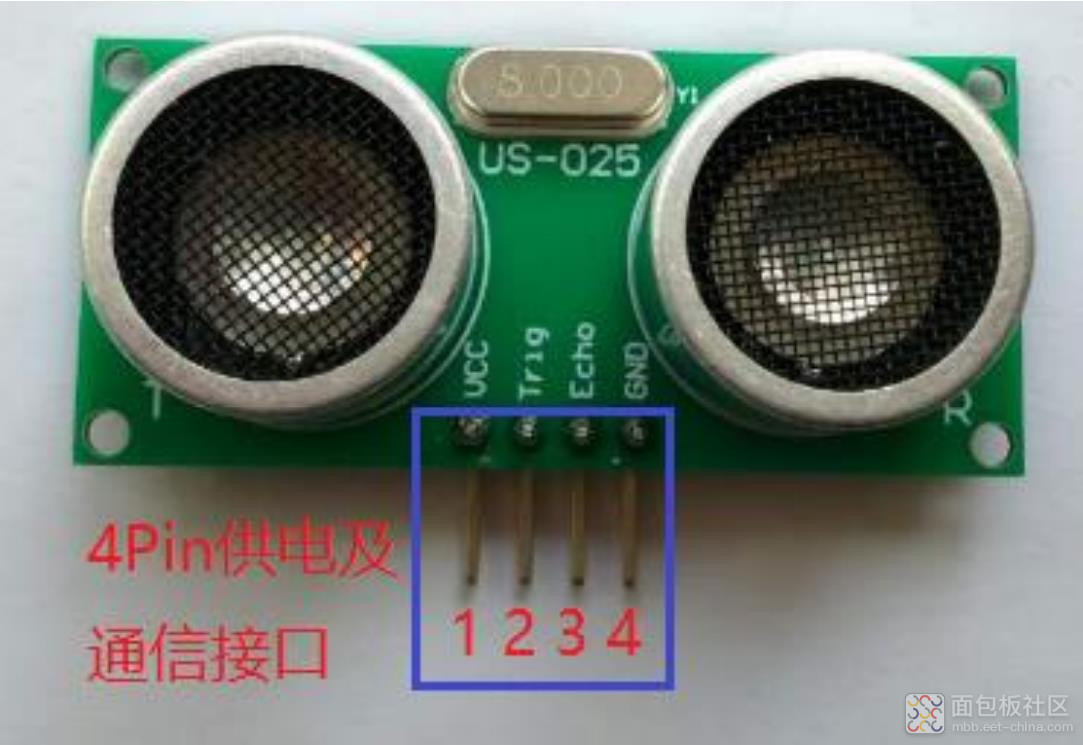
实验开源代码(Arduino 1.8.19) /* 【Arduino】168种传感器模块系列实验(资料代码+仿真编程+图形编程)实验一百零六:US-026超声波测距传感器模块 代替HC-SR04 工业级 3V~5.5V1、实验项目:US-025/US-026高精度测距例程2、实验接脚:EchoPin = D2TrigPin = D3GND = GNDVCC = 5V*/unsigned int EchoPin = 2;unsigned int TrigPin = 3;unsigned long Time_Echo_us = 0;unsigned long Len_mm_X100 = 0;unsigned long Len_Integer = 0;unsigned int Len_Fraction = 0;void setup(){Serial.begin(9600);pinMode(EchoPin, INPUT);pinMode(TrigPin, OUTPUT);}void loop(){digitalWrite(TrigPin, HIGH);delayMicroseconds(50);digitalWrite(TrigPin, LOW);Time_Echo_us = pulseIn(EchoPin, HIGH);if((Time_Echo_us < 60000) && (Time_Echo_us > 1)){Len_mm_X100 = (Time_Echo_us*34)/2;Len_Integer = Len_mm_X100/100;Len_Fraction = Len_mm_X100%100;Serial.print("Present Length is: ");Serial.print(Len_Integer, DEC);Serial.print(".");if(Len_Fraction < 10)Serial.print("0");Serial.print(Len_Fraction, DEC);Serial.println("mm");}delay(1000);}复制代码
实验开源代码(Arduino 1.8.19)之二 /* 【Arduino】168种传感器模块系列实验(资料代码+仿真编程+图形编程)实验一百零六:US-026超声波测距传感器模块 代替HC-SR04 工业级 3V~5.5V1、实验项目之二:US-025/US-026高精度测距例程22、实验接脚:EchoPin = D2TrigPin = D3GND = GNDVCC = 5V*/unsigned int EchoPin = 2; // connect Pin 2(Arduino digital io) to Echo at US-025/US-026unsigned int TrigPin = 3; // connect Pin 3(Arduino digital io) to Trig at US-025/US-026unsigned long Time_Echo_us = 0;unsigned long Len_mm = 0;void setup(){ //Initialize Serial.begin(9600); //Serial: output result to Serial monitor pinMode(EchoPin, INPUT); //Set EchoPin as input, to receive measure result from US-025,US-026 pinMode(TrigPin, OUTPUT); //Set TrigPin as output, used to send high pusle to trig measurement (>10us)}void loop(){ digitalWrite(TrigPin, HIGH); //begin to send a high pulse, then US-025/US-026 begin to measure the distance delayMicroseconds(20); //set this high pulse width as 20us (>10us) digitalWrite(TrigPin, LOW); //end this high pulse Time_Echo_us = pulseIn(EchoPin, HIGH); //calculate the pulse width at EchoPin, if((Time_Echo_us < 60000) && (Time_Echo_us > 1)) //a valid pulse width should be between (1, 60000). { Len_mm = (Time_Echo_us*34/100)/2; //calculate the distance by pulse width, Len_mm = (Time_Echo_us * 0.34mm/us) / 2 (mm) Serial.print("Present Distance is: "); //output result to Serial monitor Serial.print(Len_mm, DEC); //output result to Serial monitor Serial.println("mm"); //output result to Serial monitor } delay(1000); //take a measurement every second (1000ms)}复制代码
实验开源代码(Arduino 1.8.19)之三 /* 【Arduino】168种传感器模块系列实验(资料代码+仿真编程+图形编程)实验一百零六:US-026超声波测距传感器模块 代替HC-SR04 工业级 3V~5.5V1、实验项目之三:用串口显示测出的距离值2、实验接脚:EchoPin = D2TrigPin = D3GND = GNDVCC = 5V*/// 设定US-026连接的Arduino引脚const int TrigPin = 3;const int EchoPin = 2;float distance;void setup(){ // 初始化串口通信及连接的引脚 Serial.begin(9600); pinMode(TrigPin, OUTPUT); // 要检测引脚上输入的脉冲宽度,需要先设置为输入状态 pinMode(EchoPin, INPUT); Serial.println("Ultrasonic sensor:");}void loop(){ // 产生一个10us的高脉冲去触发TrigPin digitalWrite(TrigPin, LOW); delayMicroseconds(2); digitalWrite(TrigPin, HIGH); delayMicroseconds(10); digitalWrite(TrigPin, LOW); // 检测脉冲宽度,并计算出距离 distance = pulseIn(EchoPin, HIGH) / 58.00; Serial.print(distance); Serial.print("cm"); Serial.println(); delay(1000);}复制代码
实验串口返回情况 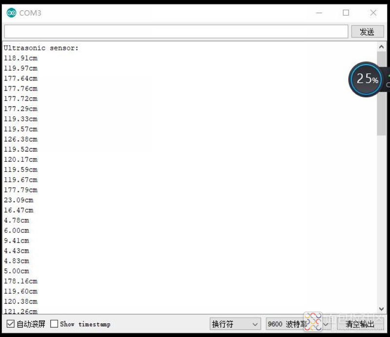
实验开源图形编程(Mind+、编玩边学) 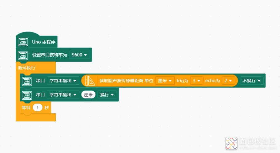
实验串口返回情况 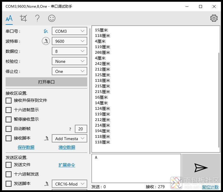
实验开源图形编程(Mind+、编玩边学)之二 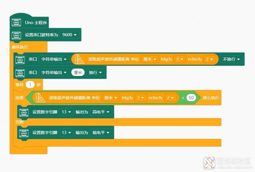
实验串口返回情况(距离小于50厘米时LED点亮) 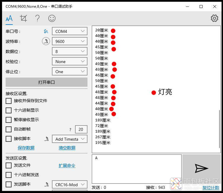 、 、
实验开源图形编程(Mind+、编玩边学)之三 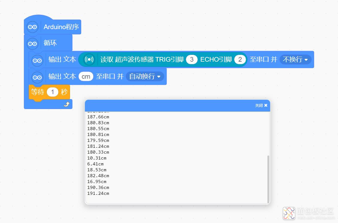
实验开源仿真编程(Linkboy V4.63) 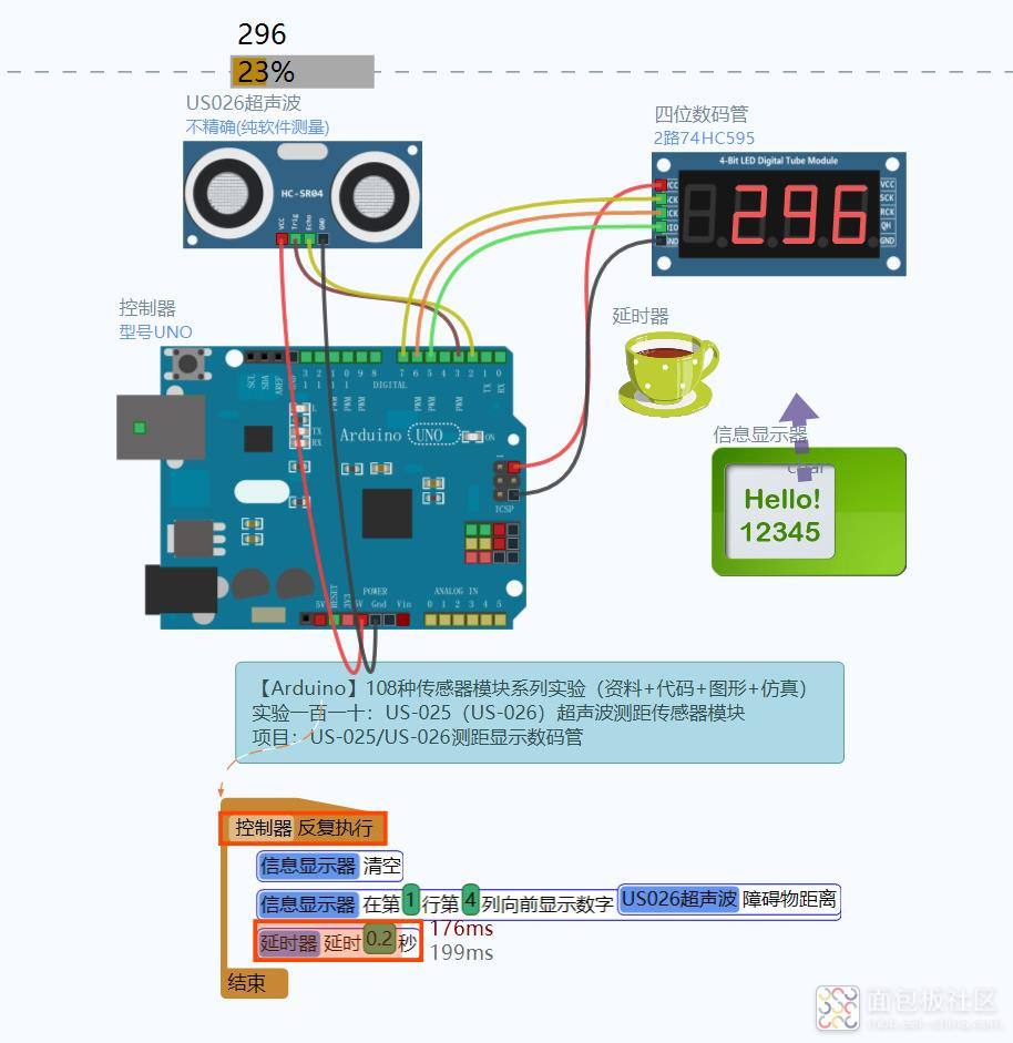
实验开源仿真编程(Linkboy V4.63)之二 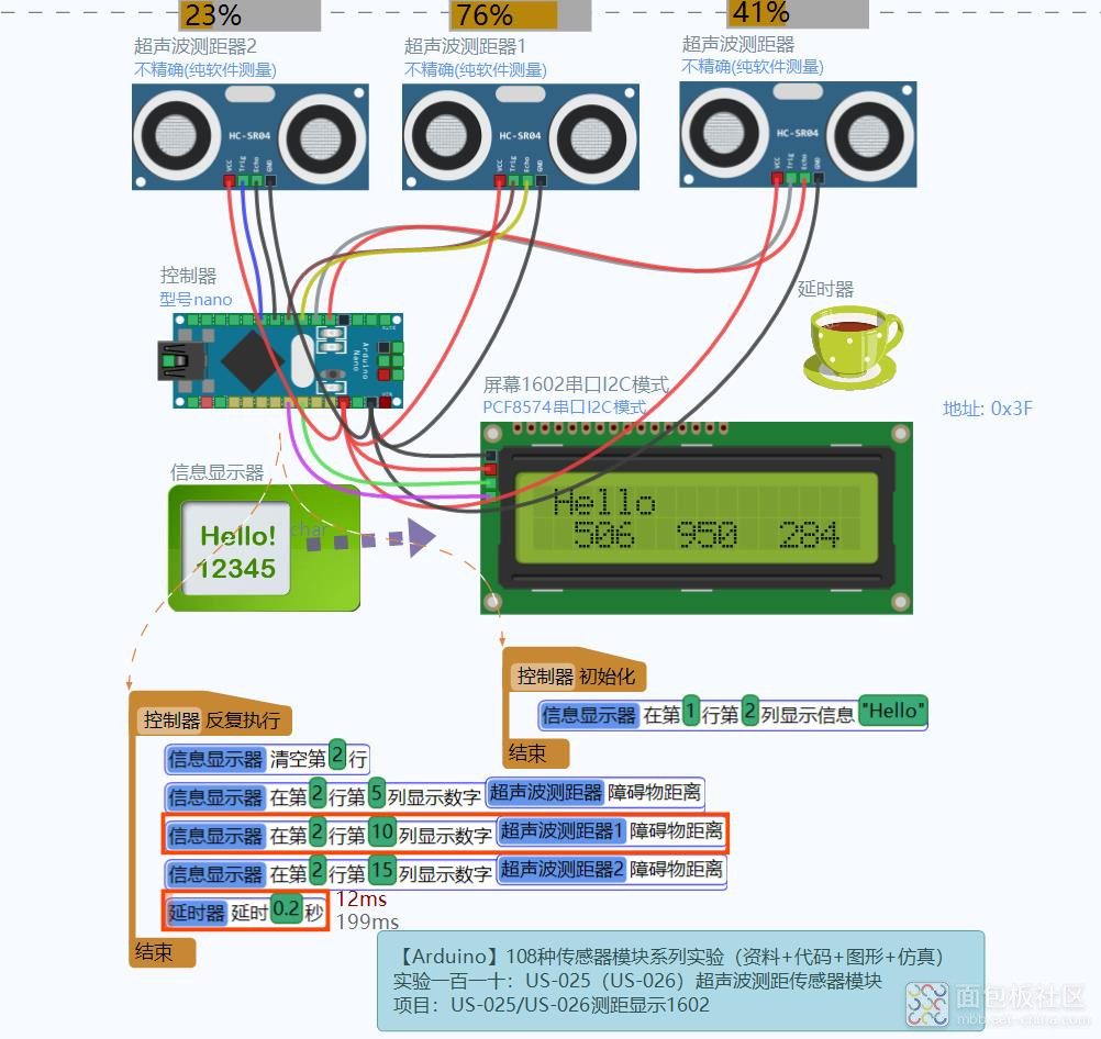
实验开源仿真编程(Linkboy V4.63)之三 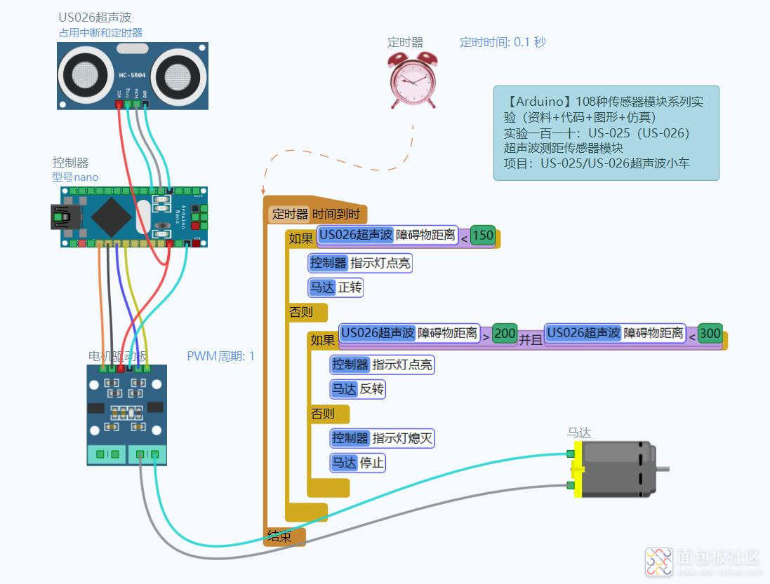
实验场景图 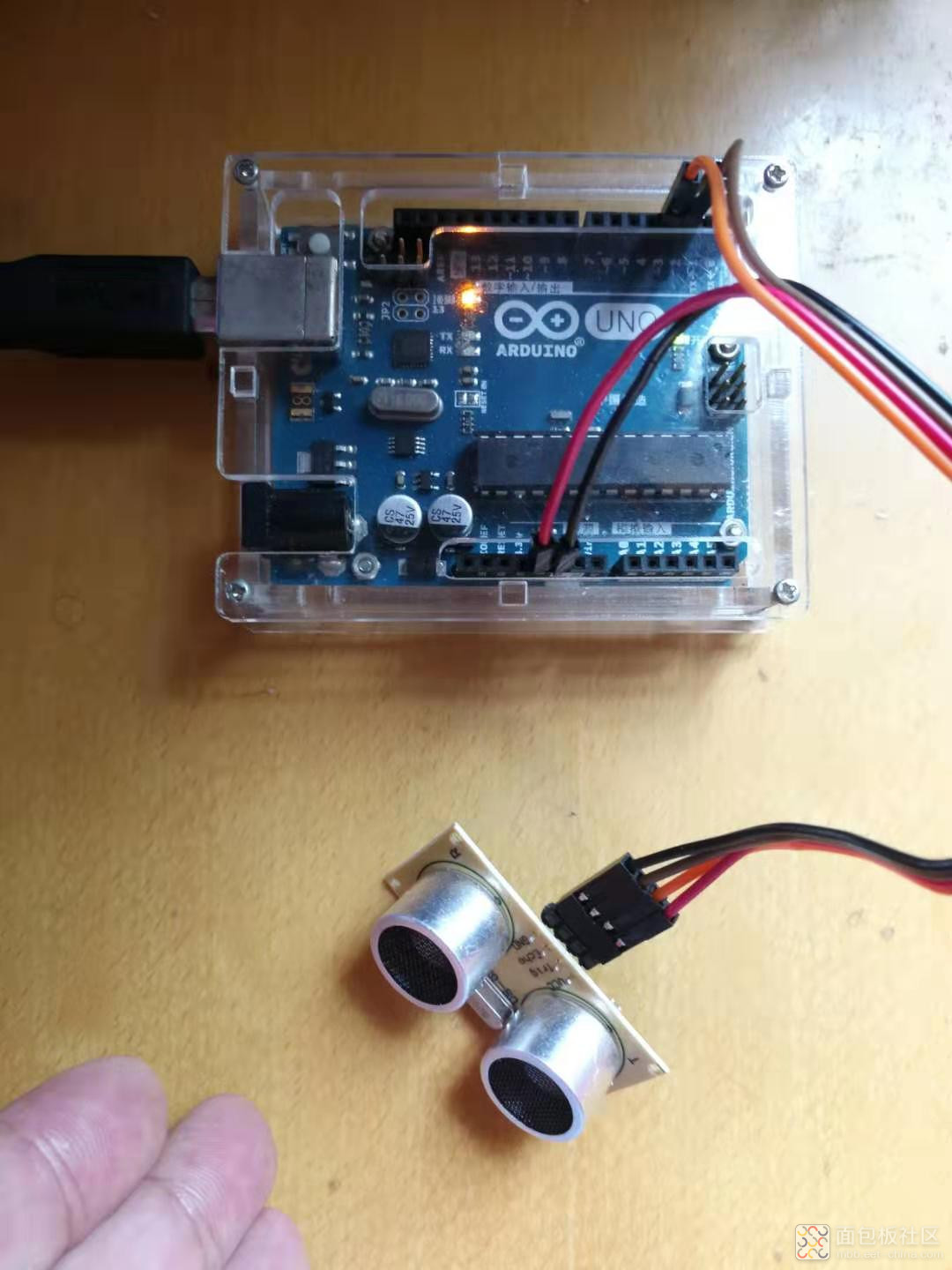
| 


 /2
/2 


yzw92 2022-8-14 08:41
curton 2022-8-13 23:04