


项目采用数字微波传感器、继电器和Arduino控制板,实现了一个对墙壁后方活动物体进行探测的自动光控系统。相较红外传感器、超声波传感器、PIR接近传感器和飞行时间(TOF)传感器方案,本项目对各种物体都敏感,而且传感器的数据不受室内温度、湿度和光线等环境因素的影响。
微波传感器是利用微波特性来检测一些物理量的器件,可感应物体的存在、运动速度、距离、角度等信息。
工作时,由发射天线发出的微波,遇到被测物体时将被吸收或反射,使功率发生变化。若利用接收天线接收通过被测物体或由被测物反射回来的微波,并将它转换成电信号,再由测量电路处理,就实现了微波检测。
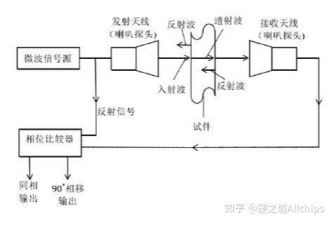
结构上,微波传感器主要由微波振荡器和微波天线组成。微波振荡器是产生微波的装置,如速调管、磁控管或某些固体元件等。微波振荡器产生的振荡信号需用波导管传输,再通过天线发射出去。为了使发射的微波具有一致的方向性,天线应具有特殊的构造和形状。
相较PIR等,微波传感器性能不受光纤、温度、湿度、噪声、灰尘等影响,广泛应用于液位检测、自动洗衣机、车速测量、自动门运动检测、车辆倾覆、生产线材料检测、自动灯控、高阶安防警报系统等。
使用来自DFrobot的重力数字微波传感器V2.0,可非接触检测任何物体,其读数不受温度、湿度、噪声、空气、灰尘和光线的影响,具有较强的抗RF干扰能力,非常适合苛刻环境应用。由于输出功率小,对人体没有伤害,加上检测范围宽,还可用来检测非生命类物体。
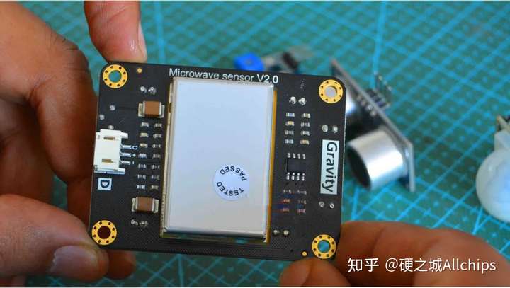
主要特点包括:
工作电压:5V
工作电流:最大60mA,典型值为37mA。
探测距离:2-16米,可通过电位器调节。
探测角度:与天线并行方向72°,垂直方向为36°。
发射: 辐射频率: 10.525GHz
调频精度: 3MHz
输出功率(Minimum): 13dBm EIRP
谐波辐射: <-10dBm
平均电流: 2mA typ.
脉冲宽度(Min.): 5uSec
负荷周期(Min.): 1%
接收: 敏感度(10dB信噪比) 3Hz to 80Hz带宽: -86dBm
3Hz to 80Hz 带宽簇: 10uV
天线增益: 8dBi
垂直3dB宽带: 36 degrees
红色LED为电源指示灯,黄色为信号指示LED。没有活动物体时间。由于没有信号,LED保持熄灭状态,只有传感器检测到活动物体时点亮。
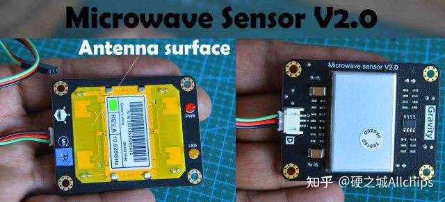
黄色PCB为天线接口板,红色引线为5V,黑色线为GND,绿色线为输出。
微波传感器光线的“ON”持续时间可按照需求进行改变,采用更高阶微波传感器可获得更高级的性能体验。
项目要求每隔3秒,就通过OLED显示模块显示一下发生中断的数目。这些中断只在出现移动物体,或者人体时才发生,数字越大意味着运动越多。
微波传感器的探测距离为2-16米,模块上的蓝色电位器就是用来调节测量距离的。
为了测试传感器性能,我将其固定在房门上,安装时要将微波传感器的正面朝向被检测区域,看看能否检测到弟弟的活动。
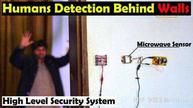
果然,传感器成功检测到了房间里的弟弟。
这下,我们来构建一个自动光控系统。这个电路比较简单,微波传感器的输出引脚连接于D2开发板的D2引脚,5v及GND两个引脚分别连接于Arduino的5v和GND引脚。
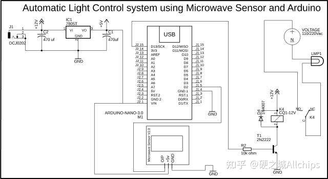
电路图左上侧是基于LM7805稳压器的5V稳定电压,J1是DC电源的母头。这里,我们连接了一个12v适配器、锂离子电池,或者太阳能电池板。
电路图右侧为12v继电器模块,连接与Arduino板子的13引脚。该继电器用来控制灯泡,其地线直接连接灯泡,火线要通过继电器连接到灯泡上。
以下是本光控系统的代码:
#include //Timer interrupt function library
int pbIn = 0; // Define interrupt 0 that is digital pin 2
int ledOut = 13; // Define the indicator LED pin digital pin 13
int number=0; //Interrupt times
volatile int state = LOW; // Defines the indicator LED state, the default is not bright
void setup()
{
Serial.begin(9600);
pinMode(ledOut, OUTPUT);//
attachInterrupt(pbIn, stateChange, FALLING); // Set the interrupt function, interrupt pin is digital pin D2,
//interrupt service function is stateChange (), when the D2 power
//change from high to low , the trigger interrupt.
MsTimer2::set(1000, Handle); // Set the timer interrupt function, running once Handle() function per 1000ms
MsTimer2::start();//Start timer interrupt function
}
void loop()
{
Serial.println(number); // Printing the number of times of interruption, which is convenient for debugging.
delay(1);
if(state == HIGH) //When a moving object is detected, the ledout is automatically closed after the light 2S,
//the next trigger can be carried out, and No need to reset. Convenient debugging.
{
delay(2000);
state = LOW;
digitalWrite(ledOut, state); //turn off led
}
}
void stateChange() //Interrupt service function
{
number++; //Interrupted once, the number + 1
}
void Handle() //Timer service function
{
if(number>2) //If in the set of the interrupt time the number more than 2 times, then means have detect moving objects,
//This value can be adjusted according to the actual situation, which is equivalent to adjust the threshold
//of detection speed of moving objects.
{
state = HIGH;
digitalWrite(ledOut, state); //light led
number=0; //Cleare the number, so that it does not affect the next trigger
}
else
number=0; //If in the setting of the interrupt time, the number of the interrupt is not
//reached the threshold value,
//it is not detected the moving objects, Clear the number.
}
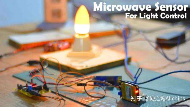
这样,我将传感器安装在房门里面,再通过Arduino加装一个蜂鸣器,只要人来到房间门口,灯光就会亮起来,并蜂鸣提示。
 /2
/2 
文章评论(0条评论)
登录后参与讨论