

个人认为,《Finite State Machine Datapath Design,Optimization,and Implementation》是一本较好的分析系统时序特性的书籍。
下面把这本书中有用的一些重要概念列出来:
CHAPTER 1
Calculating Maximum Clock Frequency
1.1GATE PROPAGATION DELAY
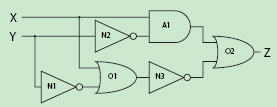
tpd---the time an input changes to the time an output changes. This delay is called the propagation delay(tpd).
Example1:

1.2FLIP-FLOP PROPAGATION DELAY
tpd--- tpd is measured from the time the clock changes to the time the input is copied to the output( usually refer as tC2Q).
synchronous input---When an input is dependant on the clock edge, it is called a synchronous input.
asynchronous input---When an input is not dependant on the clock, it is called an asynchronous input
tsu---the signal must remain at a stable logic level for a set amount of time
before the clock edge occurs. This is called the setup (tsu) time for the register.
thd---the input signal must remain stable for a set amount of time after the clock edge occurs. This is called the hold (thd) time for the register.
1.3SEQUENTIAL SYSTEMDELAY
Three types:
tP2P---A pin-to-pin propagation delay path (tP2P) is defined by any path from an input to an output that passes through only combinational gates, which means it cannot pass through any registers.
tC2Q--- the clock-to-output path (tC2Q) pass through exactly one register. The clock input is routed to the registers in the circuit. A path is traced from the clock input of the system to the clock input of a register. Then the path continues through that register to the output of the circuit.The delays of the combinational gates along the path and the clock-to-output
delay of the register are added to the total delay of the path.
tcomb I2C + tC2Q FF + tcomb Q2O = tC2Q SYS
tR2R--- the register-to-register delay (tR2R)is usually the largest of the three types of delays in modern circuit designs. this delay path starts at the output of a register and is traced to the input of another register. The path could even be traced back to the input of the starting register, but the route always involves at most two registers.
Example2:
tP2P
tC2Q
tR2R
Setup and hold adjustments
simplified model:

Calculating adjusted setup/hold times
(tpd_data(MAX) - tpd_clk(MIN)) + tsu_FF = tsu_TOTAL
(tpd_clk(MAX) - tpd_data(MIN)) + thd_FF = thd_TOTAL
tsu_TOTAL/tsu_TOTAL---caculated system total setup/hold time;
tpd_data---delay from the data input to the registers
tpd_clk---delay from the clock input to the registers
tsu_FF /thd_FF ---setup/hold time of Flip-Flops
use Example2 to caculate:
tsu_TOTAL=(tpd_data_U1 - tpd_clk_U1)) + tsu_FF=(9-2) + 3 = 10 ns
thd_TOTAL=(tpd_clk(MAX) -tpd_data(MIN)) +tsu_FF=(2 -8) + 4 = -2 ns
The setup and hold window is 8 ns in which the data cannot change. The negative sign in
the hold time calculation means the data input can actually start changing before the clock signal.This is not an intuitive behavior for a digital circuit, so often a negative thd will be specified as zeroinstead. By setting thd to zero, the effective setup and hold window has increased to 10 ns.
 /1
/1 
文章评论(0条评论)
登录后参与讨论