

NI Multisim software offers advanced virtual instruments and
analyses to help you gain a deeper and more complex understanding of the
operation of your design.
One of these tools, the measurement probe, can be a quick and
functional interface to the characteristics of your circuit as well as
an advanced tool to customize the simulation process in Multisim. With
the advanced features of the probe, you can use the instantaneous
voltages and currents at a particular node to access and display
information in the Description Edit Box and pause your simulation as
discussed in this article.
An important feature for many designers, the measurement probe provides quick access to the voltage, current, and frequency of a particular node during simulation. You can easily place multiple instances of the probe at any node of a circuit from the Instruments toolbar (circled in red in Figure 1).

Figure 1. Use the Instruments toolbar to place multiple instances of the measurement probe at any node.
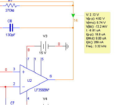
Once a probe is connected to a node on a Multisim schematic, a yellow data region immediately communicates the time-varying characteristics of the circuit as shown in Figure 2.

Figure 2. Communicating the Time-Varying Characteristics of the Circuit
The measurement probe's advanced features can also assist you in analyzing and customizing the simulation of a circuit. For example, you can set your simulation to pause based on a predetermined condition so you can check that a circuit is functioning properly during set increments of simulation.
This example uses the Speechfilter.ms10 file, a sample file included with Multisim 10.0.
1. Select File?Open Samples and open the Speechfilter.ms10 file.
2. Click on the Measurement Probe tool in the Instruments toolbar. Notice that the mouse cursor has changed to the probe mode.
3. Connect the measurement probe to net 14 as shown in Figure 2 by left-clicking on the wire.
4. Notice that a new yellow field is now displayed on the schematic with the measurement labels for voltage (V), peak-to-peak voltage (Vpk-pk), and so on.
In the Probe Properties dialog box, you can set the probe to pause simulation for a discrete amount of time when net 14 reaches a certain voltage value (in this case, whenever you reach a value greater than 2 V).
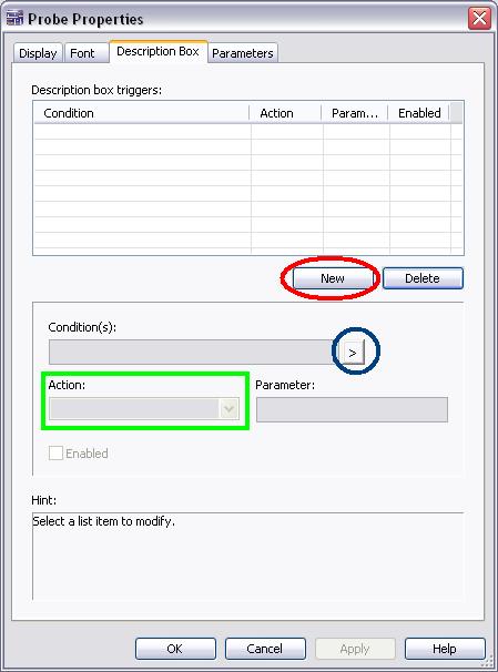
5. Double-click on the yellow measurement probe field and select the Description Box tab. The tab looks like the image in Figure 3.

Figure 3. Description Box Tab in the Probe Properties Dialog Box
6. To add a pause condition, click on the New button (circled in red in Figure 3). This enables the settings in the bottom of the window to build the final expression.
You can enter the condition at which an action is taken in one of two ways: manually enter it into the Condition(s) field OR enter it via pop-up menus as described below.
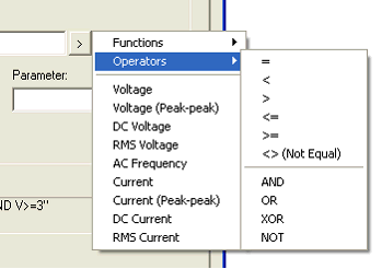
7. To create the mathematical expression or Condition(s), click on the arrow button (circled in blue in Figure 3). This displays the information shown in Figure 4.

Figure 4. Creating a Mathematical Expression
8. Select the Voltage heading in the pop-up menu. Notice that the value V has now been populated in the Condition(s) field.
9. Click on the arrow button (circled in blue in Figure 3) and select the Operators heading. In the pop-up menu, select the > (greater than) sign. Notice that the Conditions field now reads V>.
10. Finally select the Conditions field with a left-click of the mouse and type the value 2.
You have just created the condition for your measurement probe. You are
now ready to select the action to be taken when the condition is met.
11. Select the Action combo box (circled in green in Figure 3).
12. In the drop-down box, select the Pause Simulation option.
Simulation automatically pauses as soon as the voltage is at any value greater than 2 V. You can now set the length of the pause, five seconds.
13. Select the Parameter field and enter the value 5.
14. Click on the Apply button.
15. Click on the OK button.
Simulate the circuit and notice in the measurement probe that at each
point that Multisim simulates a voltage value greater than 2 V at node 14,
the simulator pauses. If multiple probes are placed in the schematic,
this five-second pause allows any designer to quickly take stock of the
characteristics of a circuit during simulation, ensuring that when node 14 reaches the preset condition, there is an opportunity to check other currents and voltages of interest.
总之,探针的条件性可以很方便地实现对某个变量的条件值监测,对高速电路仿真时也很方便。
 /4
/4 
文章评论(0条评论)
登录后参与讨论