


从本文开始,后续文章着重学习fpga的内部组成 电源特性和时序优化 验证等内容
本文内容
---fpga电源设计注意事项
---cyclone II 供电分析
---FPGA电源解决方案
---Cyclone II 电源特性(数据手册第四第五章 第七章)
---Cyclone II 电源管脚:
---数据手册中电源参数:
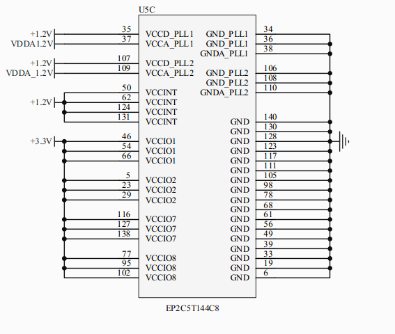
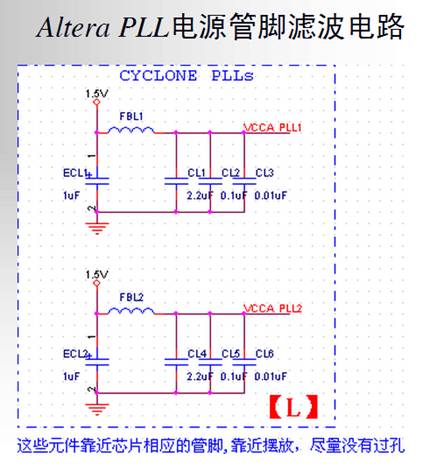
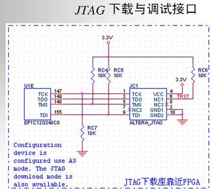
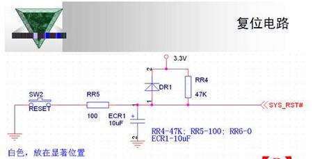
---可参考电路
参考资料
文章
http://www.fpga-cpld.com/artical/fpga/019/
http://www.ti.com.cn/lsds/ti_zh/analog/webench/fpga-power-architect.page
http://www.21ic.com/app/eda/201206/128072.htm
从零开始设计FPGA最小系统
http://pan.baidu.com/share/link?shareid=1467781286&uk=590284399&fid=945219091
QUARTUS POWERPLAY 用户手册
http://www.altera.com/literature/hb/qts/qts_qii53013.pdf
ALTERA电源方案中心
http://www.altera.com/support/devices/power/pow-power.html
合作伙伴电源方案
http://www.altera.com/support/devices/vendors/pow-vendors.html
cyclone II 电源比较
http://www.altera.com/devices/fpga/cyclone2/features/power/cy2-power-compare.html
为FPGA系统设计一个稳定可靠地电源并不是一件简单的事情。
作为系统的动力,电源的可靠性直接应将系统的稳定和可靠运行。
而fpga供电与一般的系统不同,fpga往往内核电压低,且IO与内核等部分分别供电,这就对电源的上升时间和纹波系数要更高的特殊要求。为保证FPGA正常启动,内核电压VCCINT的上升时间tr必须在特定的范围内。电压上升必须单调,不允许有波动。过长的缓升时间可能会导致启动电流持续较长时间。如果电源向FPGA提供大电流,则较长的上电缓升时间会引起热应力设计经验表明,大部分情况下内核电压VCCINT先于I/O电压VCCO供给是比较好的做法。
注意事项:
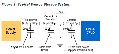
在设计可编程门阵列(FPGA)电路时,必须极端重视电源问题,从而使最终产品能在所有可能的工作条件下无缺陷和处于最优状态。FPGA 电路电源有两项需考虑的问题: FPGA 电路上电
要求和FPGA电路功率分析。
FPGA电路有多路电源输入。为优化开机接通时的电流拖曳,防止锁死和永久性的电路损坏,这些电源输入必须有精确的上电序列和/ 或正确的电压变化率。如果FPGA电路包括一片或多片专用集成电路(ASIC),或需要配置与FPGA 通信的器件,上电过程也许相当复杂。在这种情况下,可能要在FPGA自身完全配置前或配置后,依照某种时序给其它器件上电。同时也需要防止开机接通时的毛刺干扰和降低开机接通的功耗。如果FPGA在开机时发生问题,比如锁死,稳压电路也不能为调试提供多少有用信息。
FPGA电路的功耗与几项因素,特别是与其设计相关。这些因素包括配置FPGA 所使用硬件描述语言的优化质量,与I/O 的连接接口,以及I/O 流量的频率。您需要在所有可能工作条件下测试FPGA电路功耗,从而确定设计必须提供的最大电源功耗。
FPGA电路的初步功率分析采用估算算法。您可在FPGA制造商提供的文档中找到这些算法。估算算法的精度很低。它的主要目的是为设计师在考虑功率分配时,提供估计FPGA电路平均功耗和最坏条件功耗的一个起算点。有些FPGA制造商更进一步提供用于功耗计算的软件工具。(Cyclone II PowerPlay功耗估算)
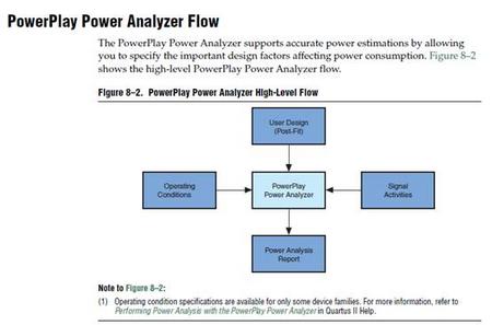
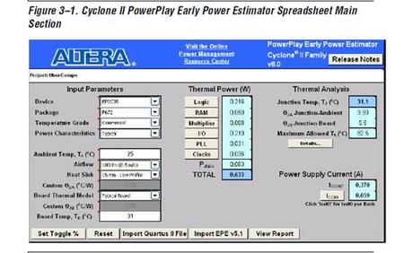
CYCLONE II电源主要分为:内核电源,IO电源,PLL电源,参考电压,JTAG/AS电源
内核电压
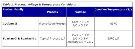
内核电压通常设定成VCCINT,为FPGA逻辑供电。通常为1.5V或1.2V,要求的电流从几百毫安到几十安培,具体大小取决于时钟频率和所用的门数。因为该负载是呈高度容性,内核电压电流要求可能在开始的时候很高。FPGA内核对瞬态响应的要求很严格,内核电源电压必须缓慢增加并且常常要求在固定的时间长度内上升到稳定的电压。
I/O电压
I/O电压(VCCIO)通常要求的电压轨是3.3V、2.5V、1.8V或1.5V。I/O标准可以由FPGA中的I/O模块独立设置,因此一个FPGA就有可能存在一个以上的I/O电压。I/O电流要求取决于所用的I/O数量和时钟速度。通常,I/O电流要求低,范围在几百毫安到3A。
辅助电压
辅助电压(VCCREF)要求电源具有高电源抑制比(PSRR),因为电源直接与数字时钟管理(DCM)相连。如果电源噪声被容许耦合到DCM,将可能影响到系统的性能。
虽然I/O和辅助电压不需要按照特别的顺序上电,但是,FPGA制造商常常要指定内核和I/O的上电顺序或跟踪该顺序。不指定上电顺序或不跟踪上电顺序所面临的后果是常常会对系统中的器件造成不可挽回的破坏。FPGA、PLD、DSP和微处理器通常在内核与I/O电源之间放置二极管作为ESD保护元件。如果电源违反了跟踪要求并超过了保护二极管的正向偏置,那么该器件就可能被损坏。
现有的FPGA电源解决方案
根据采用FPGA系列的不同,核心和I/O电压可能是2.5V,1.8V,1.5V和1.2V,目前总的来说有三种电源解决方案,分别是线性稳压器电源(LDO),开关稳压器电源(DC/DC调整器和DC/DC控制器,两者的差别主要是内部是否集成FETs),电源模块。在选择方案时,要求设计者综合考虑系统要求,成本,效率,市场需要,设计灵活性及封装等众多因素。
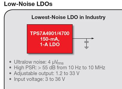
目前的电源器件都在往大范围电压输入,低噪音,低压输出方面发展.
这里参考下TI的方案进行讨论
http://www.ti.com/lit/sg/slyt525/slyt525.pdf
(资料中还附带了时钟和高速AD DA方案)
比如LDO输入电压3-36v输出33-1.2v 另外其他的很多电源芯片也支持大范围电压输入比如lm2575 lm2596等
还有一些大家经常用到的AMS1117系列的电压最高推荐不超过15v输出分可调和固定电压1.2V 1.5V 1.8V 2.5V 3.0V 3.3V 5.0V等。也可满足一般的设计.
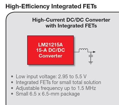
DC/DC
Cyclone II 电源特性(数据手册第四 第五章第七章)
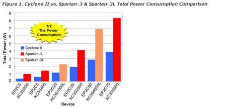
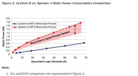
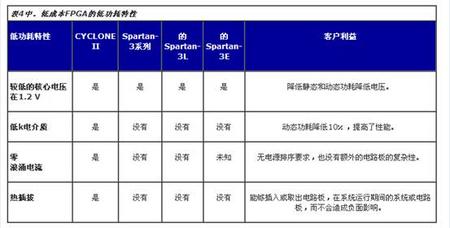
1/2 the Static Power 1/2 the Dynamic Power Zero Inrush Current Hot-Socketing Support Fewer Required Power Supplies
The Cyclone II Total Advantage
#1 in Low Power—Half the power of competing 90-nm low-cost FPGAs.
#1 in Price—No price premiums for lower power. Competing 90-nm low-cost FPGAs have a price premium to obtain lower power devices.
#1 in Performance—60 percent higher performance than competing 90-nm low-cost FPGAs. Obtain low power and high performance from a single FPGA.
另外Cyclone还有防浪涌,热插拔,上电复位,PLL电源,以及其他IO方面的电源特性
比如
The IOE registers in each I/O block share the same source for clear or
preset. You can program preset or clear for each individual IOE, but both
features cannot be used simultaneously. You can also program the
registers to power up high or low after configuration is complete. If
programmed to power up low, an asynchronous clear can control the
registers. If programmed to power up high, an asynchronous preset can
control the registers. This feature pr events the inadvertent activation of
another device’s active-low input upon power up. If one register in an
IOE uses a preset or clear signal then all registers in the IOE must use that
same signal if they require preset or clear. Additionally a synchronous
reset signal is availabl e for the IOE registers.
Cyclone 电源管脚:
VCCINT:内核电压。通常与FPGA芯片所采用的工艺有关,例如130nm工艺为1.5V,90nm工艺为1.2V。
VCCIO:端口电压。一般为3.3V,还可以支持选择多种电压,如1.8V、1.5V等。
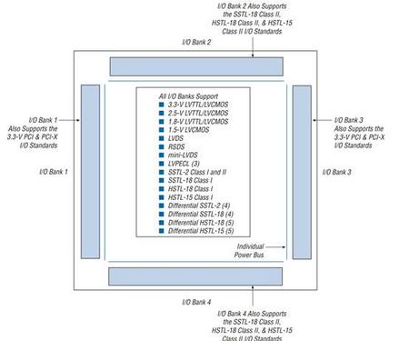
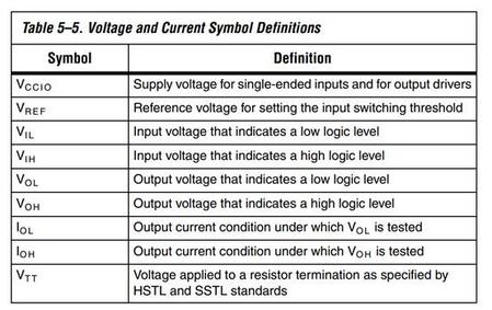
VREF:参考电压。
VCC_PLL:锁相环管脚电压,直接连VCCIO。
VCCA_PLL:锁相环模拟电压,一般通过滤波器接到VCCINT上。
GNDA_PLL:锁相环模拟地。
GNDD_PLL:锁相环数字地。
JTAG AS VCC电源
最小系统设计可参考
http://wenku.baidu.com/view/a52f7b87ec3a87c24028c421.html
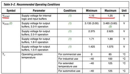
数据手册中电源参数:
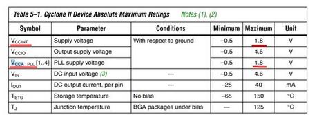
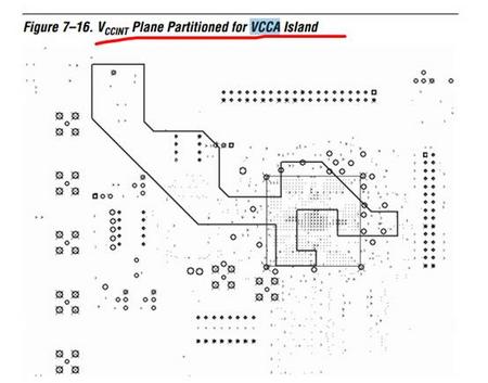
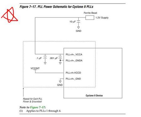
Each Cyclone II PLL uses separate VCC and ground pin pairs for their
analog circuitry. The anal og circuit power and ground pin for each PLL is
called VCCA_PLL < PLL number> and GNDA_ PLL< PLL number>. Connect
the VCCA power pin to a 1.2-V power supply, even if you do not use the
PLL. Isolate the power connected to VCCA from the power to the rest of
the Cyclone II device or any other digi tal device on the board. You can use
one of three different method s of isolating the VCCA pin:
■ Use separate VCCA power planes
■ Use a partitioned VCCA island within the VCCINT plane
■ Use thick VCCA traces
MultiVolt I/O Interface(P2-60)
The Cyclone II architecture supports the MultiVolt I/O interface feature,
which allows Cyclone II devices in all packages to interface with systems
of different supply voltages. Cyclone II devices have one set of V
CC
pins
( VCCINT) that power the internal device logic array and input buffers that
use the LVPECL, LVDS, HSTL, or SSTL I/O standards. Cyclone II devices
also have four or eight sets of VCC pins (VCCIO ) that power the I/O
output drivers and input buffers that use the LVTTL, LVCMOS, or PCI
I/O standards.
The Cyclone II VCCINT pins must always be co nnected to a 1.2-V power
supply. If the V
CCINT
level is 1.2 V, then input pi ns are 1.5-V, 1.8-V, 2.5-V,
and 3.3-V tolerant. The VCCIO pins can be connected to either a 1.5-V,
1.8-V, 2.5-V, or 3.3-V power supply, depending on the output
requirements. The output levels are co mpatible with systems of the same
voltage as the power supply (i.e., when VCCIO pins are connected to a
1.5-V power supply, the output levels are compatible with 1.5-V systems).
When VCCIO pins are connected to a 3.3-V power supply, the output high
is 3.3-V and is compatible with 3.3-V systems.
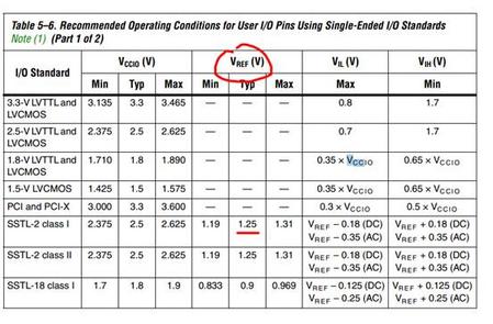
Each I/O bank has its own VCCIO pins. A single de vice can support
1.5-V, 1.8-V, 2.5-V, and 3.3-V interfac es; each individual bank can support
a different standard with different I/O voltages. Each bank also has
dual-purpose VREF pins to support any one of the voltage-referenced
standards (e.g., SSTL-2) independently. If an I/O bank does not use
voltage-referenced standards, the VREF pins are available as user I/O
pins.
Each I/O bank can support multiple standards with the same VCCIO for
input and output pins. For example, when V
CCIOis 3.3-V, a bank can support LVTTL, LVCMOS, and 3.3-V PCI for inputs and outputs.
Voltage-referenced standards can be supported in an I/O bank using any
number of single-ended or differential standards as long as they use the
same VREF and a compatible VCCIO value.
The Cyclone II architecture supports the MultiVolt I/O interface feature,
which allows Cyclone II devices in all packages to interface with systems
of different supply voltages. Cyclone II devices have one set of VCC pins
( VCCINT) that power the internal device logic array and input buffers that
use the LVPECL, LVDS, HSTL, or SSTL I/O standards. Cyclone II devices
also have four or eight sets of VCC pins (VCCIO ) that power the I/O
output drivers and input buffers that use the LVTTL, LVCMOS, or PCI
I/O standards.
The Cyclone II VCCINT pins must always be co nnected to a 1.2-V power supply. If the V
CCINT level is 1.2 V, then input pi ns are 1.5-V, 1.8-V, 2.5-V,
and 3.3-V tolerant. The VCCIO pins can be connected to either a 1.5-V,
1.8-V, 2.5-V, or 3.3-V power supply, depending on the output
requirements. The output levels are co mpatible with systems of the same
voltage as the power supply (i.e., when VCCIO pins are connected to a
1.5-V power supply, the output levels are compatible with 1.5-V systems).
When VCCIO pins are connected to a 3.3-V power supply, the output high
is 3.3-V and is compatible with 3.3-V systems.
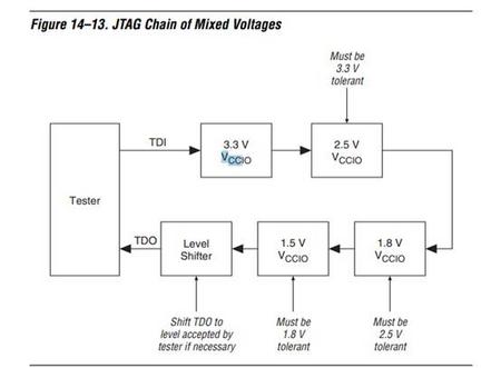
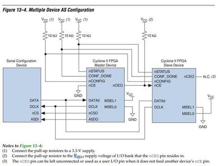
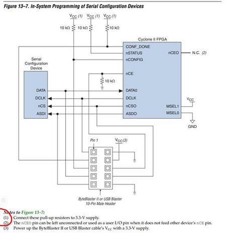
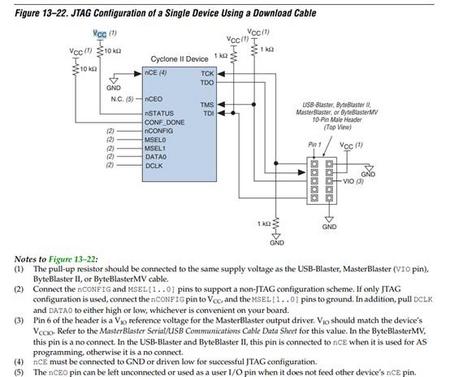
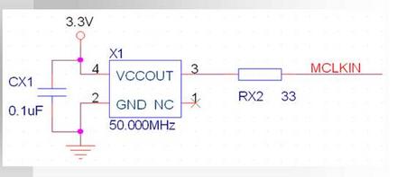
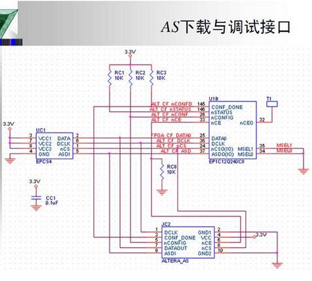
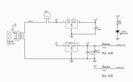
可参考参考电路
 /5
/5 
文章评论(0条评论)
登录后参与讨论