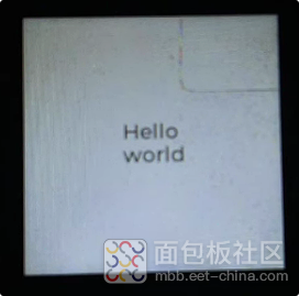
SPI概述 ESP IDF中SPI LCD的相关API 简单使用LVGL 完整代码 总结 SPI概述 当进入嵌入式行业开始,SPI总线是最需要且基础的知识了,它是高速全双工串行总线,可做到同时收发数据。时序和控制根据各家的芯片或者屏幕等设备的数据手册进行阅读和进行编程,比如总线模式就有四种,通过寄存器CPOL和CPHA配置 模式 CPOL CPHA 数据采样时刻 适用场景 0 0 0 SCK下降沿,第1个跳变沿采样 多数传感器(如BME280) 1 0 1 SCK下降沿,第2个跳变沿采样 部分ADC芯片 2 1 0 SCK上升沿,第1个跳变沿采样 特殊存储器 3 1 1 SCK上升沿,第2个跳变沿采样 某些RF模块 更多的SPI相关基础,可以在网上查询 ESP IDF中SPI LCD相关API 在ESP32开发库ESP IDF中有完整的SPI LCD实现的代码,我们只需要合适的调用相关API函数就可以了,在此案例中用到如下函数和结构体 1. 配置SPI总线 SPI总线结构体 typedef struct { union { int mosi_io_num; //spi的mosi接口,不用赋值-1 int data0_io_num; /// GPIO pin for spi data0 signal in quad/octal mode, or -1 if not used. }; union { int miso_io_num; /// GPIO pin for Master In Slave Out (=spi_q) signal, or -1 if not used. int data1_io_num; /// GPIO pin for spi data1 signal in quad/octal mode, or -1 if not used. }; int sclk_io_num; /// GPIO pin for SPI Clock signal, or -1 if not used. union { int quadwp_io_num; /// GPIO pin for WP (Write Protect) signal, or -1 if not used. int data2_io_num; /// GPIO pin for spi data2 signal in quad/octal mode, or -1 if not used. }; union { int quadhd_io_num; /// GPIO pin for HD (Hold) signal, or -1 if not used. int data3_io_num; /// GPIO pin for spi data3 signal in quad/octal mode, or -1 if not used. }; int data4_io_num; /// GPIO pin for spi data4 signal in octal mode, or -1 if not used. int data5_io_num; /// GPIO pin for spi data5 signal in octal mode, or -1 if not used. int data6_io_num; /// GPIO pin for spi data6 signal in octal mode, or -1 if not used. int data7_io_num; /// GPIO pin for spi data7 signal in octal mode, or -1 if not used. int max_transfer_sz; /// Maximum transfer size, in bytes. Defaults to 4092 if 0 when DMA enabled, or to `SOC_SPI_MAXIMUM_BUFFER_SIZE` if DMA is disabled. uint32_t flags; /// Abilities of bus to be checked by the driver. Or-ed value of ``SPICOMMON_BUSFLAG_*`` flags. esp_intr_cpu_affinity_t isr_cpu_id; /// Select cpu core to register SPI ISR. int intr_flags; /** Interrupt flag for the bus to set the priority, and IRAM attribute, see * ``esp_intr_alloc.h``. Note that the EDGE, INTRDISABLED attribute are ignored * by the driver. Note that if ESP_INTR_FLAG_IRAM is set, ALL the callbacks of * the driver, and their callee functions, should be put in the IRAM. */ } spi_bus_config_t ; 初始化SPI总线函数 esp_err_t spi_bus_initialize ( spi_host_device_t host_id, //使用哪个主机SPI,有SPI0_HOST、SPI1_HOST、SP2_HOST const spi_bus_config_t *bus_config, //使用spi_bus_config_t创建的结构体 spi_dma_chan_t dma_chan //dma通道,设置SPI_DMA_DISABLED则不开启 ) 2. 创建LCD SPI句柄,并与SPI总线相连 LCD SPI面板相关io结构体 typedef struct { int cs_gpio_num; /*! GPIO used for CS line */ int dc_gpio_num; /*! GPIO used to select the D/C line, set this to -1 if the D/C line is not used */ int spi_mode; /*! Traditional SPI mode (0~3) */ unsigned int pclk_hz; /*! Frequency of pixel clock */ size_t trans_queue_depth; /*! Size of internal transaction queue */ esp_lcd_panel_io_color_trans_done_cb_t on_color_trans_done; /*! Callback invoked when color data transfer has finished */ void *user_ctx; /*! User private data, passed directly to on_color_trans_done's user_ctx */ int lcd_cmd_bits; /*! Bit-width of LCD command */ int lcd_param_bits; /*! Bit-width of LCD parameter */ struct { unsigned int dc_low_on_data: 1 ; /*! If this flag is enabled, DC line = 0 means transfer data, DC line = 1 means transfer command; vice versa */ unsigned int octal_mode: 1 ; /*! transmit with octal mode (8 data lines), this mode is used to simulate Intel 8080 timing */ unsigned int quad_mode: 1 ; /*! transmit with quad mode (4 data lines), this mode is useful when transmitting LCD parameters (Only use one line for command) */ unsigned int sio_mode: 1 ; /*! Read and write through a single data line (MOSI) */ unsigned int lsb_first: 1 ; /*! transmit LSB bit first */ unsigned int cs_high_active: 1 ; /*! CS line is high active */ } flags; /*! Extra flags to fine-tune the SPI device */ } esp_lcd_panel_io_spi_config_t ; 创建LCD SPI面板相关io的句柄 esp_err_t esp_lcd_new_panel_io_spi ( esp_lcd_spi_bus_handle_t bus, //SPI总线 const esp_lcd_panel_io_spi_config_t *io_config, //填充完成的esp_lcd_panel_io_spi_config_t结构体变量 esp_lcd_panel_io_handle_t *ret_io //返回的LCD SPI面板句柄 ) //在使用这个函数之前需先创建个esp_lcd_panel_io_spi_config_t结构体变量,比如esp_lcd_panel_io_handle_t io_handle = NULL; LCD SPI面板驱动配置结构体 typedef struct { int reset_gpio_num; /*! GPIO used to reset the LCD panel, set to -1 if it's not used */ union { lcd_rgb_element_order_t color_space; /*! @deprecated Set RGB color space, please use rgb_ele_order instead */ lcd_rgb_element_order_t rgb_endian; /*! @deprecated Set RGB data endian, please use rgb_ele_order instead */ lcd_rgb_element_order_t rgb_ele_order; /*! Set RGB element order, RGB or BGR */ }; lcd_rgb_data_endian_t data_endian; /*! Set the data endian for color data larger than 1 byte */ unsigned int bits_per_pixel; /*! Color depth, in bpp */ struct { unsigned int reset_active_high: 1 ; /*! Setting this if the panel reset is high level active */ } flags; /*! LCD panel config flags */ void *vendor_config; /*! vendor specific configuration, optional, left as NULL if not used */ } esp_lcd_panel_dev_config_t ; 创建 LCD 面板句柄,并指定 SPI IO 设备句柄 以下函数是ESP IDF套件中已经实现的st7789相关函数,其内部还有很多适配的LCD,可以在如下路径找到 esp-idf/components/esp_lcd/src //其实就是将实现的st7789相关函数注册到LCD面板这个大的虚拟对象中,这是C语言的面向对象编程 esp_err_t esp_lcd_new_panel_st7789 ( const esp_lcd_panel_io_handle_t io, //创建过的lcd面板io句柄 const esp_lcd_panel_dev_config_t *panel_dev_config, //创建过的LCD面板驱动句柄 esp_lcd_panel_handle_t *ret_panel //返回一个LCD面板句柄 ) 3. 通过以上一步步完善结构体,和创建的LCD面板句柄,我们将可以调用关于LCD 面板的所有API函数,比如: //控制LCD复位 esp_err_t esp_lcd_panel_reset ( esp_lcd_panel_handle_t panel) //初始化LCD esp_err_t esp_lcd_panel_init ( esp_lcd_panel_handle_t panel) //开关屏幕 esp_err_t esp_lcd_panel_disp_on_off ( esp_lcd_panel_handle_t panel, bool on_off) //控制屏幕是否反色,白天模式暗黑模式的控制 esp_err_t esp_lcd_panel_invert_color ( esp_lcd_panel_handle_t panel, bool invert_color_data) 使用LVGL 1. 将LVGL的库加入到项目中 ESP IDF开发套件有完善的组件管理方式,在UBUNTU中我们可以如下操作 在项目根目录下使用如下命令,将会在main文件夹下生成一个idf_component.yml的文件 idf.py create-manifest 增加参数: --path:显示的指定在什么目录下创建组件清单文件 --component:在componets目录下,为相关组件创建(此参数所赋值)清单,比如--component=my_components 使用如下命令重新配置项目 idf.py reconfigure 这样就后面每次在构建项目时,则会跟踪上一步生成的idf_component.yml文件 编辑idf_component.yml ## IDF Component Manager Manifest File dependencies: ## Required IDF version idf: version: "=4.1.0" lvgl/lvgl: "~9.2.0" //这是我需要添加的LVGL库,版本时9.2.0 更多操作可以参考如下链接; https://docs.espressif.com/projects/esp-idf/zh_CN/release-v5.2/esp32s3/api-guides/tools/idf-component-manager.html 2. 使用LVGL在屏幕上显示"hello world" 初始化lvgl lv_init(); 创建lvgl显示器 lv_display_t * lv_display_create ( int32_t hor_res, int32_t ver_res) //参数为实际屏幕的分辨率 申请绘制使用的buffer void lv_display_set_buffers ( lv_display_t * disp, //上一步创建的显示器 void * buf1, //缓存1 void * buf2, //缓存2 uint32_t buf_size, //缓存大小 lv_display_render_mode_t render_mode //绘制图像的模式 ) 将LVGL与上面创建的LCD面板进行连接 void lv_display_set_user_data ( lv_display_t * disp, void * user_data) 设置显示的颜色格式 void lv_display_set_color_format ( lv_display_t * disp, lv_color_format_t color_format) 设置显示的方向 void lv_display_set_rotation ( lv_display_t * disp, lv_display_rotation_t rotation) 设置渲染回调函数 void lv_display_set_flush_cb ( lv_display_t * disp, lv_display_flush_cb_t flush_cb) //回调函数如果设置为NULL,则使用默认函数 为LVGL创建定时器 static void example_increase_lvgl_tick ( void *arg) { /* Tell LVGL how many milliseconds has elapsed */ lv_tick_inc ( 2 ); //这里是2ms,建议跟定时器定时时间同步 } const esp_timer_create_args_t lvgl_tick_timer_args = { .callback = example_increase_lvgl_tick, //定时事件,定时通知lvgl已经多久了 .name = "lvgl_tick" }; esp_timer_handle_t lvgl_tick_timer = NULL ; ESP_ERROR_CHECK ( esp_timer_create (lvgl_tick_timer_args, lvgl_tick_timer)); ESP_ERROR_CHECK ( esp_timer_start_periodic (lvgl_tick_timer, 2 * 1000 )); //2ms触发一次事件 为lvgl创建任务 //通过lv_timer_handler(void)持续更新lvgl,这是LVGL的心脏 static void example_lvgl_port_task ( void *arg) { ESP_LOGI (TAG, "Starting LVGL task" ); uint32_t time_till_next_ms = 0 ; while ( 1 ) { _lock_acquire(lvgl_api_lock); time_till_next_ms = lv_timer_handler (); _lock_release(lvgl_api_lock); // in case of triggering a task watch dog time out time_till_next_ms = MAX (time_till_next_ms, EXAMPLE_LVGL_TASK_MIN_DELAY_MS); // in case of lvgl display not ready yet time_till_next_ms = MIN (time_till_next_ms, EXAMPLE_LVGL_TASK_MAX_DELAY_MS); usleep ( 1000 * time_till_next_ms); } } xTaskCreatePinnedToCore (example_lvgl_port_task, "LVGL" , EXAMPLE_LVGL_TASK_STACK_SIZE, NULL , EXAMPLE_LVGL_TASK_PRIORITY, NULL , 1 ); 绘制显示内容,如下绘制“hello world" lv_obj_t *scr = lv_display_get_screen_active (disp); lv_obj_t *label1= lv_label_create (scr); lv_label_set_text (label1, "Hello\nworld" ); lv_obj_align (label1, LV_ALIGN_CENTER, 0 , 0 ); 完整代码 /** * Copyright (C) 2024-2034 HalfMoon2. * All rights reserved. * * @file Filename without the absolute path * @brief Brief description * @author HalfMoon2 * @date 2025-06-27 * @version v0.1 * * @revision history: * 2025-06-23 - Initial version. */ # include stdio.h # include unistd.h # include sys/lock.h # include sys/param.h # include freertos/FreeRTOS.h # include freertos/task.h # include esp_log.h # include driver/gpio.h # include driver/spi_master.h # include "driver/spi_common.h" # include "esp_timer.h" # include "esp_lcd_panel_io.h" # include "esp_lcd_panel_vendor.h" # include "esp_lcd_panel_ops.h" # include "esp_lcd_panel_commands.h" # include "esp_dma_utils.h" # include "lvgl.h" static const char *TAG = "ST7789" ; //LCD使用的SPI接口 # define LCD_SPI SPI2_HOST //SPI相关引脚定义 # define SPI_LCD_MOSI GPIO_NUM_12 # define SPI_LCD_MISO GPIO_NUM_18 # define SPI_LCD_SCLK GPIO_NUM_11 # define SPI_LCD_CS GPIO_NUM_15 # define SPI_LCD_DC GPIO_NUM_17 # define SPI_LCD_RST GPIO_NUM_21 # define SPI_LCD_BL GPIO_NUM_26 //LCD显示屏的大小 # define LCD_SIZE_WIDTH 240 # define LCD_SIZE_HIGHT 240 # define EXAMPLE_LVGL_TASK_MIN_DELAY_MS 1000/CONFIG_FREERTOS_HZ # define EXAMPLE_LVGL_TASK_MAX_DELAY_MS 500 # define EXAMPLE_LVGL_TASK_STACK_SIZE (4 * 1024) # define EXAMPLE_LVGL_TASK_PRIORITY 5 // LVGL library is not thread-safe, this example will call LVGL APIs from different tasks, so use a mutex to protect it static _lock_t lvgl_api_lock; static void set_angle ( void * obj, int32_t v) { lv_arc_set_value (obj, v); } void example_lvgl_demo_ui ( lv_display_t *disp) { lv_obj_t *scr = lv_display_get_screen_active (disp); lv_obj_t *label1= lv_label_create (scr); lv_label_set_text (label1, "Hello\nworld" ); lv_obj_align (label1, LV_ALIGN_CENTER, 0 , 0 ); } static void example_lvgl_port_task ( void *arg) { ESP_LOGI (TAG, "Starting LVGL task" ); uint32_t time_till_next_ms = 0 ; while ( 1 ) { _lock_acquire(lvgl_api_lock); time_till_next_ms = lv_timer_handler (); _lock_release(lvgl_api_lock); // in case of triggering a task watch dog time out time_till_next_ms = MAX (time_till_next_ms, EXAMPLE_LVGL_TASK_MIN_DELAY_MS); // in case of lvgl display not ready yet time_till_next_ms = MIN (time_till_next_ms, EXAMPLE_LVGL_TASK_MAX_DELAY_MS); usleep ( 1000 * time_till_next_ms); } } /* Rotate display and touch, when rotated screen in LVGL. Called when driver parameters are updated. */ static void example_lvgl_port_update_callback ( lv_display_t *disp) { esp_lcd_panel_handle_t panel_handle = lv_display_get_user_data (disp); lv_display_rotation_t rotation = lv_display_get_rotation (disp); switch (rotation) { case LV_DISPLAY_ROTATION_0: // Rotate LCD display esp_lcd_panel_swap_xy (panel_handle, false ); esp_lcd_panel_mirror (panel_handle, false , false ); break ; case LV_DISPLAY_ROTATION_90: // Rotate LCD display esp_lcd_panel_swap_xy (panel_handle, true ); esp_lcd_panel_mirror (panel_handle, true , true ); break ; case LV_DISPLAY_ROTATION_180: // Rotate LCD display esp_lcd_panel_swap_xy (panel_handle, false ); esp_lcd_panel_mirror (panel_handle, true , true ); break ; case LV_DISPLAY_ROTATION_270: // Rotate LCD display esp_lcd_panel_swap_xy (panel_handle, true ); esp_lcd_panel_mirror (panel_handle, true , false ); break ; } } static void example_increase_lvgl_tick ( void *arg) { /* Tell LVGL how many milliseconds has elapsed */ lv_tick_inc ( 1 ); } static void example_lvgl_flush_cb ( lv_display_t *disp, const lv_area_t *area, uint8_t *px_map) { example_lvgl_port_update_callback (disp); esp_lcd_panel_handle_t panel_handle = lv_display_get_user_data (disp); int offsetx1 = area-x1; int offsetx2 = area-x2; int offsety1 = area-y1; int offsety2 = area-y2; // because SPI LCD is big-endian, we need to swap the RGB bytes order lv_draw_sw_rgb565_swap (px_map, (offsetx2 + 1 - offsetx1) * (offsety2 + 1 - offsety1)); // copy a buffer's content to a specific area of the display esp_lcd_panel_draw_bitmap (panel_handle, offsetx1, offsety1, offsetx2 + 1 , offsety2 + 1 , px_map); } static esp_lcd_panel_handle_t st7789_init ( void ) { //spi bus的相关配置 spi_bus_config_t busconfig={ // .flags=SPICOMMON_BUSFLAG_MASTER, //设置SPI为主机模式 .sclk_io_num=SPI_LCD_SCLK, .miso_io_num=SPI_LCD_MISO, .mosi_io_num=SPI_LCD_MOSI, .quadwp_io_num = -1 , .quadhd_io_num = -1 , .max_transfer_sz=LCD_SIZE_HIGHT*LCD_SIZE_WIDTH* sizeof ( uint16_t ) //单次最多可传输80行像素 }; ESP_ERROR_CHECK ( spi_bus_initialize (LCD_SPI, busconfig, SPI_DMA_CH_AUTO)); // 启用 DMA //创建SPI LCD句柄 esp_lcd_panel_io_handle_t io_handle = NULL ; esp_lcd_panel_io_spi_config_t io_config = { .dc_gpio_num = SPI_LCD_DC, .cs_gpio_num = SPI_LCD_CS, .pclk_hz = 40 * 1000 * 1000 , .lcd_cmd_bits = 8 , .lcd_param_bits = 8 , .spi_mode = 0 , .trans_queue_depth = 10 }; // 将 LCD 连接到 SPI 总线 ESP_ERROR_CHECK ( esp_lcd_new_panel_io_spi (( esp_lcd_spi_bus_handle_t )LCD_SPI, io_config, io_handle)); esp_lcd_panel_handle_t panel_handle = NULL ; esp_lcd_panel_dev_config_t panel_config = { .reset_gpio_num = SPI_LCD_RST, .rgb_ele_order = LCD_RGB_ELEMENT_ORDER_BGR, .bits_per_pixel = 16 , }; // 为 ST7789 创建 LCD 面板句柄,并指定 SPI IO 设备句柄 ESP_ERROR_CHECK ( esp_lcd_new_panel_st7789 (io_handle, panel_config, panel_handle)); ESP_ERROR_CHECK ( esp_lcd_panel_reset (panel_handle)); ESP_ERROR_CHECK ( esp_lcd_panel_init (panel_handle)); ESP_ERROR_CHECK ( esp_lcd_panel_disp_on_off (panel_handle, true )); esp_lcd_panel_invert_color (panel_handle, true ); ESP_LOGI (TAG, "Initialize LVGL library" ); return panel_handle; } void app_main ( void ) { esp_lcd_panel_handle_t panel_handle= st7789_init (); lv_init (); // create a lvgl display lv_display_t *display = lv_display_create ( 240 , 240 ); // alloc draw buffers used by LVGL // it's recommended to choose the size of the draw buffer(s) to be at least 1/10 screen sized size_t draw_buffer_sz = 240 * 240 * sizeof ( lv_color16_t ); void *buf1 = heap_caps_malloc (draw_buffer_sz, MALLOC_CAP_DMA); assert (buf1); void *buf2 = heap_caps_malloc (draw_buffer_sz, MALLOC_CAP_DMA); assert (buf2); // initialize LVGL draw buffers lv_display_set_buffers (display, buf1, buf2, draw_buffer_sz, LV_DISPLAY_RENDER_MODE_PARTIAL); // associate the mipi panel handle to the display lv_display_set_user_data (display, panel_handle); // set color depth lv_display_set_color_format (display, LV_COLOR_FORMAT_RGB565); // set the callback which can copy the rendered image to an area of the display lv_display_set_rotation (display,LV_DISPLAY_ROTATION_0); lv_display_set_flush_cb (display, example_lvgl_flush_cb); ESP_LOGI (TAG, "Install LVGL tick timer" ); // Tick interface for LVGL (using esp_timer to generate 2ms periodic event) const esp_timer_create_args_t lvgl_tick_timer_args = { .callback = example_increase_lvgl_tick, .name = "lvgl_tick" }; esp_timer_handle_t lvgl_tick_timer = NULL ; ESP_ERROR_CHECK ( esp_timer_create (lvgl_tick_timer_args, lvgl_tick_timer)); ESP_ERROR_CHECK ( esp_timer_start_periodic (lvgl_tick_timer, 2 * 1000 )); ESP_LOGI (TAG, "Create LVGL task" ); xTaskCreatePinnedToCore (example_lvgl_port_task, "LVGL" , EXAMPLE_LVGL_TASK_STACK_SIZE, NULL , EXAMPLE_LVGL_TASK_PRIORITY, NULL , 1 ); ESP_LOGI (TAG, "Display LVGL Meter Widget" ); // Lock the mutex due to the LVGL APIs are not thread-safe _lock_acquire(lvgl_api_lock); example_lvgl_demo_ui (display); _lock_release(lvgl_api_lock); } 显示结果: 总结 一定要注意以下几点: 缓存区大小的设定,如果设置不正确将会出现如下情况,偏移也会如此,所以碰到这个情况可以想想会不会是缓存区的问题 显示镜像,根据不同的实现方式,要仔细调试 //这里只是设置了标志 lv_display_set_rotation (display,LV_DISPLAY_ROTATION_0); //要通过如下函数进行具体实现 static void example_lvgl_port_update_callback ( lv_display_t *disp) { esp_lcd_panel_handle_t panel_handle = lv_display_get_user_data (disp); lv_display_rotation_t rotation = lv_display_get_rotation (disp); switch (rotation) { case LV_DISPLAY_ROTATION_0: // Rotate LCD display esp_lcd_panel_swap_xy (panel_handle, false ); esp_lcd_panel_mirror (panel_handle, false , false ); break ; case LV_DISPLAY_ROTATION_90: // Rotate LCD display esp_lcd_panel_swap_xy (panel_handle, true ); esp_lcd_panel_mirror (panel_handle, true , true ); break ; case LV_DISPLAY_ROTATION_180: // Rotate LCD display esp_lcd_panel_swap_xy (panel_handle, false ); esp_lcd_panel_mirror (panel_handle, true , true ); break ; case LV_DISPLAY_ROTATION_270: // Rotate LCD display esp_lcd_panel_swap_xy (panel_handle, true ); esp_lcd_panel_mirror (panel_handle, true , false ); break ; } } static void example_lvgl_flush_cb ( lv_display_t *disp, const lv_area_t *area, uint8_t *px_map) { example_lvgl_port_update_callback (disp); esp_lcd_panel_handle_t panel_handle = lv_display_get_user_data (disp); int offsetx1 = area-x1; int offsetx2 = area-x2; int offsety1 = area-y1; int offsety2 = area-y2; // because SPI LCD is big-endian, we need to swap the RGB bytes order lv_draw_sw_rgb565_swap (px_map, (offsetx2 + 1 - offsetx1) * (offsety2 + 1 - offsety1)); // copy a buffer's content to a specific area of the display esp_lcd_panel_draw_bitmap (panel_handle, offsetx1, offsety1, offsetx2 + 1 , offsety2 + 1 , px_map); } 如下情况,就需要改example_lvgl_port_update_callback函数里的具体实现 esp idf开发套件里有大量的案例,完全可以参考相关代码进行设计,当然从零搭建也是可以的,如果时间充裕的话 lvgl的相关配置,可以使用idf.py menuconfig进行更改


 标签: freertos