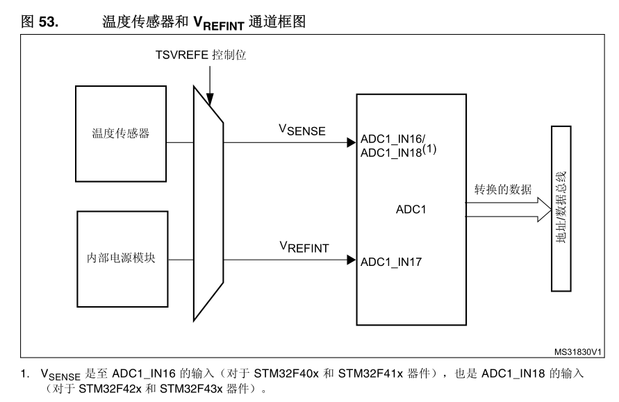
01. 内部温度传感器简介STM32F4 有一个内部的温度传感器,可以用来测量 CPU 及周围的温度(TA)。该温度传感器在内部和 ADC1_IN16(STM32F40xx/F41xx 系列)或 ADC1_IN18(STM32F42xx/F43xx系列)输入通道相连接,此通道把传感器输出的电压转换成数字值。 STM32F4 的内部温度传感器支持的温度范围为:-40~125 度。精度为±1.5℃左右。02. 主要特性和框图● 支持的温度范围:—40 °C 到 125 °C● 精度:±1.5 °C 读取温度要使用传感器,请执行以下操作:选择 ADC1_IN16 或 ADC1_IN18 输入通道。选择一个采样时间,该采样时间要大于数据手册中所指定的最低采样时间。在 ADC_CCR 寄存器中将 TSVREFE 位置 1,以便将温度传感器从掉电模式中唤醒。通过将 SWSTART 位置 1(或通过外部触发)开始 ADC 转换读取 ADC 数据寄存器中生成的 V SENSE 数据使用以下公式计算温度:温度(单位为 °C)= {(V SENSE — V 25 ) / Avg_Slope} + 25其中:— V 25 = 25 °C 时的 V SENSE 值— Avg_Slope = 温度与 V SENSE 曲线的平均斜率(以 mV/°C 或 μV/°C 表示)有关 V 25 和 Avg_Slope 实际值的相关信息,请参见数据手册中的电气特性一节。温馨提示传感器从掉电模式中唤醒需要一个启动时间,启动时间过后其才能正确输出 V SENSE 。 ADC 在上电后同样需要一个启动时间,因此,为尽可能减少延迟间,应同时将 ADON 和 TSVREFE位置 1温度传感器的输出电压随温度线性变化。由于工艺不同,该线性函数的偏移量取决于各个芯片(芯片之间的温度变化可达 45 °C)。内部温度传感器更适用于对温度变量而非绝对温度进行测量的应用情况。如果需要读取精确温度,则应使用外部温度传感器。03. 硬件模块用到的硬件资源有:1) 指示灯 DS02) TFTLCD 模块3) ADC4) 内部温度传感器04. 编程步骤① 选择ADC_IN16或者ADC_IN16输入通道。② 设置采样时间大于17.1us。③ 设置ADC_CCR的TSVREFE位,打开内部温度传感器。④ 设置ADC_CR2的SWSTART位启动转换。⑤ 读取ADC结果。⑥ 计算。05. 程序示例初始化函数//ADC通道初始化void ADC1_Init(void){ GPIO_InitTypeDef GPIO_InitStructure; ADC_CommonInitTypeDef ADC_CommonInitStructure; ADC_InitTypeDef ADC_InitStructure; //开启GPIO时钟 PA5 RCC_AHB1PeriphClockCmd(RCC_AHB1Periph_GPIOA, ENABLE); //开启ADC1时钟 RCC_APB2PeriphClockCmd(RCC_APB2Periph_ADC1, ENABLE); //GPIO初始化 初始化为模拟功能 GPIO_InitStructure.GPIO_Pin = GPIO_Pin_5; GPIO_InitStructure.GPIO_Mode = GPIO_Mode_AN; GPIO_InitStructure.GPIO_PuPd = GPIO_PuPd_UP; GPIO_Init(GPIOA, &GPIO_InitStructure); RCC_APB2PeriphResetCmd(RCC_APB2Periph_ADC1,ENABLE); //ADC1复位 RCC_APB2PeriphResetCmd(RCC_APB2Periph_ADC1,DISABLE); //复位结束 //使能内部温度传感器 ADC_TempSensorVrefintCmd(ENABLE); //初始化ADC_CCR寄存器 ADC_CommonInitStructure.ADC_Mode = ADC_Mode_Independent; ADC_CommonInitStructure.ADC_TwoSamplingDelay = ADC_TwoSamplingDelay_5Cycles; ADC_CommonInitStructure.ADC_DMAAccessMode = ADC_DMAAccessMode_Disabled; ADC_CommonInitStructure.ADC_Prescaler = ADC_Prescaler_Div4; ADC_CommonInit(&ADC_CommonInitStructure); //初始化ADC1 ADC_InitStructure.ADC_Resolution = ADC_Resolution_12b; ADC_InitStructure.ADC_ScanConvMode = DISABLE; ADC_InitStructure.ADC_ContinuousConvMode = DISABLE; ADC_InitStructure.ADC_ExternalTrigConvEdge = ADC_ExternalTrigConvEdge_None; ADC_InitStructure.ADC_DataAlign = ADC_DataAlign_Right; ADC_InitStructure.ADC_NbrOfConversion = 1; ADC_Init(ADC1, &ADC_InitStructure); //设置ADC规则组通道 一个序列 采样时间 ADC_RegularChannelConfig(ADC1, ADC_Channel_5, 1, ADC_SampleTime_480Cycles); ADC_RegularChannelConfig(ADC1, ADC_Channel_16, 1, ADC_SampleTime_480Cycles); //使能ADC ADC_Cmd(ADC1, ENABLE);}获取温度值的函数//获取温度值s16 Get_Temperature(void){ u32 value = 0; s16 result = 0; double temperature = 0; //读取通道16内部温度传感器的值 value = Get_Adc_Average(ADC_Channel_16, 10); //转化为电压值 temperature = (float)value * (3.3 / 4096); //转化为温度值 temperature = (temperature - 0.76) / 0.0025 + 25; temperature *= 100; result = temperature; return result;}主函数#include "sys.h"#include "delay.h"#include "usart.h"#include "led.h"#include "beep.h"#include "key.h"#include "usmart.h"#include "lcd.h"#include "rtc.h"#include "rng.h"#include "key.h"#include "wkup.h"#include "adc.h"int main(void){ //u16 value = 0; s16 temp = 0; NVIC_PriorityGroupConfig(NVIC_PriorityGroup_2);//设置系统中断优先级分组2 delay_init(168); uart_init(115200); //usmart_dev.init(84); LED_Init(); LCD_Init(); ADC1_Init(); POINT_COLOR = RED; LCD_ShowString(30,50,200,16,16,"Explorer STM32F4"); LCD_ShowString(30,70,200,16,16,"Temperature TEST"); LCD_ShowString(30,90,200,16,16,"ATOM@tom"); LCD_ShowString(30,110,200,16,16,"2020/09/13"); //设置字体为蓝色 POINT_COLOR = BLUE; LCD_ShowString(30,140,200,16,16,"Temperate:00.00C"); while(1) { //得到温度值 temp = Get_Temperature(); printf("temperature: %f\r\n", (float)temp / 100); LED1 = !LED1; delay_ms(250); }}
关闭
站长推荐
 /4
/4 


 /4
/4 
文章评论(0条评论)
登录后参与讨论