

中文版见: http://blog.ednchina.com/likee/111649/message.aspx
A VGA monitor requires 5 signals to display a picture:
R, G and B (red, green and blue signals).
HS and VS (horizontal and vertical synchronization).

The R, G and B are analog signals, while HS and VS are digital signals.
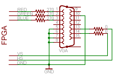
Here's how to drive the VGA connector:
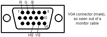
Pins 13 and 14 of the VGA connector (HS and VS) are digital signals, so can be driven directly from two FPGA pins (or through low values resistors, like 10? or 20?).
Pins 1, 2 and 3 (R, G and B) are 75? analog signals with nominal values of 0.7V. With 3.3V FPGA outputs, use three 270? series resistors. The resistors form voltage dividers with the 75? resistors in the monitor inputs so that 3.3V become 3.3*75/(270+75)=0.72V, pretty close to 0.7V. Driving these 3 pins with different combinations of 0's and 1's gives us up to 8 colors.
Ground pins are pins 5, 6, 7, 8 and 10.
Scan type: non interlaced.
Sync polarity: H negative, V negative.

 /4
/4 
文章评论(0条评论)
登录后参与讨论