原创
【数字IC】高级数字 IC 设计(4)灰度转二值化设计
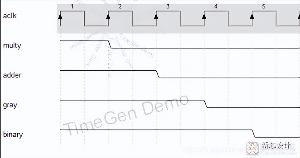
这是一个能够成功上板实现的灰度转二值的 Verilog 程序设计,详细的数据延时与信号延时如下所示:

首先是输入 RGB 数据信号在第一个时钟上升沿到来的时候,开始从前级的模块输入到后级的模块。此时,乘法打一拍、加法打一拍、灰度打一拍、二值打一拍。这样,经过一系列操作,直到最终的二值输出,中间经历了 4 个时钟的延时。因此,行场同步控制信号也需要 4 个时钟的延时来和 RGB 数据同步。
RTL 代码
|
Plaintext
module Gray_Binary(
input wire aclk,
input wire aresetn,
input wire [23:0] rgb,
input wire i_h_sync,
input wire i_v_sync,
output reg binary,
output reg o_h_sync,
output reg o_v_sync
);
reg [15:0] multy1,multy2,multy3;
reg [15:0] adder;
reg [7:0] gray;
wire [7:0] i_r_8b;
wire [7:0] i_g_8b;
wire [7:0] i_b_8b;
assign i_r_8b = rgb[23:16];
assign i_g_8b = rgb[15:8];
assign i_b_8b = rgb[7:0];
reg i_h_sync_delay_1;
reg i_h_sync_delay_2;
reg i_h_sync_delay_3;
reg i_v_sync_delay_1;
reg i_v_sync_delay_2;
reg i_v_sync_delay_3;
always @(posedge aclk)begin
multy1 <= i_r_8b * 8'd76;
multy2 <= i_g_8b * 8'd150;
multy3 <= i_b_8b * 8'd30;
end
always @(posedge aclk)begin
adder <= multy1 + multy2 + multy3;
end
always @(posedge aclk)begin
gray <= adder[15:8];
end
always @(posedge aclk)begin
binary <= (gray<8'd58)?1'b1:1'b0;
end
always @(posedge aclk or negedge aresetn) begin
if(!aresetn)begin
i_h_sync_delay_1<=0;
i_h_sync_delay_2<=0;
i_h_sync_delay_3<=0;
i_v_sync_delay_1<=0;
i_v_sync_delay_2<=0;
i_v_sync_delay_3<=0;
end
else begin
i_h_sync_delay_1 <= i_h_sync;
i_h_sync_delay_2 <= i_h_sync_delay_1;
i_h_sync_delay_3 <= i_h_sync_delay_2;
o_h_sync <= i_h_sync_delay_3;
i_v_sync_delay_1 <= i_v_sync;
i_v_sync_delay_2 <= i_v_sync_delay_1;
i_v_sync_delay_3 <= i_v_sync_delay_2;
o_v_sync <= i_v_sync_delay_3;
end
end
endmodule
|


 /4
/4 
文章评论(0条评论)
登录后参与讨论