加载方法
ZYNQ的启动镜像是由FSBL程序(bootloader),PL配置文件(硬件比特流文件),应用层软件三个部分组成,其通过SDK的软件生成工具把三个部分按规定的格式拼凑成一个.bin文件,最终将这个文件写入到QSPIFLASH中,整个ZYNQ在配置好启动方式为FLASH启动后,便可做到上电自启动运行下载到FLASH中的用户程序。
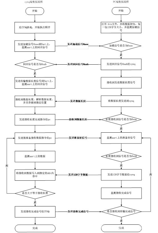
为了实现远程加载,抛开仿真器,通过UART的方式将固定的.bin文件发送给ZYNQ,然后将文件写入到FLASH。其分三个步骤完成整个程序的更新:第一,搭建UART的传输,通过规定的握手协议,PC机将.bin文件以串口的形式发送给ZYNQ;第二,ZYNQ将收到的文件存储在指定的DDR3内存当中;第三,ZYNQ将DDR3中的文件数据写入到FLASH,写完以后在读出来与接收的数据作对比,做一个校验。
串口交互形式
-
开启PC机加载程序,等待任务机发送加载信号;
-
ZYNQ上电后第一时间给UART发送加载信号0xee,随后监测UART上的回应信号;
-
PC机监测UART上的加载信号,若是0xee,则发送回应信号0xab,表示PC机做好了进入加载的准备,若不是0xee则不会发送回应信号;
-
ZYNQ收到回应信息0xab以后,进入加载流程,发送获取长度指令信号0xcc给PC机;
-
PC机监测UART上的获取长度指令信号,若是0xcc,则发送数据总包数n给PC机(长度=128*n);
-
ZQNY收到数据长度数据后,发送应答信号0xaa给PC机,表示接收到数据长度了;
-
PC机监测UART上的应答信号,接收到应答信号0xaa后,PC机进入发送数据流程,监测ZYNQ的准备好接收数据信号0xdd;
-
ZYNQ接收完数据长度以后,发送准备好接收数据信号0xdd给PC机;
-
PC机监测UART上的准备好接收数据信号0xdd,收到准备好信号0xdd信号以后,发送一包数据(128byte)给ZYNQ,发送完了以后又监测准备好信号0xdd,然后又发送一包数据(128byte)给ZYNQ,往复循环,直到数据包发送完,发送完数据后监测数据接收完信号0xbb;
-
ZYNQ接收完数据后,发送接收完信号0xbb给PC机;
-
PC机监测数据接收完信号0xbb;收到接收完信号0xbb后,数据交互流程完成,ZYNQ监测FLASH写入操作完成信号;
-
ZYNQ将接收到的数据写入到FLASH,写入完了以后发送FLASH写入操作完成信号0xaf给PC机;
-
PC机监测到接收完成信号0xaf后,提示用户写flash操作完成;进入到监测FLASH数据校验阶段;
-
ZYNQ写完flash后,将对应数据从flash中读出来做校验,校验成功则发送校验完成信号0xcf给PC机,若校验失败则发送失败信号0xef给PC机;
-
PC机监测到校验完成信号或者校验失败信号后提示用户校验完成,整个加载程序完成。
交互流程如图1所示。
UART与QSPI读写函数的设计
Uart初始化流程
-
通过uart设备ID找到对应的外设信息;
-
填充uart外设寄存器基地址和一些相关信息;
-
uart外设自检;
-
配置uart的fifo的触发等级;
-
使能uart外设;
源码如下
void Init_Uart(void)
{
XUartPs_Config *UartConifgPtr;
s32 temp;
//find device
UartConifgPtr = XUartPs_LookupConfig (XPAR_PS7_UART_1_DEVICE_ID);
//config xuartps data struct
XUartPs_CfgInitialize(&Uart_1,UartConifgPtr, UartConifgPtr->BaseAddress);
//self test
temp = XUartPs_SelfTest(&Uart_1);
if(temp != XST_SUCCESS)
{
return;
}
// XUartPs_SetDataFormat(&Uart_1,XUARTPS_FORMAT_EVEN_PARITY);
//set uart fifo level
XUartPs_SetFifoThreshold(&Uart_1,8);
//uart enable
XUartPs_EnableUart(&Uart_1);
}
Uart接收字节函数
判断RX的FIFO是否为空,如果处于空的状态,一直等待;如果不为空,读取RX的FIFO里面的数据,源码如下:
u8 Uart_RecvByte(void)
{
u8 byte = 0;
while((((XUartPs_ReadReg(InstancePtr->Config.BaseAddress,XUARTPS_SR_OFFSET)) & 0x02) == 0x02));
byte = XUartPs_ReadReg(InstancePtr->Config.BaseAddress,XUARTPS_FIFO_OFFSET);
return byte;
}
Uart发送字节函数
判断TX的FIFO是否满,如果处于满的状态,一直等待;如果未满,则把需要发送的数据写入到TX的FIFO中,源码如下:
void Uart_SendByte(u8 byte)
{
while((((XUartPs_ReadReg(InstancePtr->Config.BaseAddress,XUARTPS_SR_OFFSET)) & 0x10) == 0x10));
XUartPs_WriteReg(InstancePtr->Config.BaseAddress,XUARTPS_FIFO_OFFSET,byte);
}
初始化QSPI流程
-
通过qspi设备ID找到对应的外设信息;
-
填充qspi外设寄存器基地址和一些相关信息;
-
Qspi外设自检;
-
配置qspi的工作模式;
-
配置qspi的工作频率;
-
配置qspi的为从设备选择;
源码如下:
void Init_Qspi(void)
{
XQspiPs_Config *QspiConfig;
//find device
QspiConfig = XQspiPs_LookupConfig(XPAR_XQSPIPS_0_DEVICE_ID);
//config XQspiPs data struct QspiInstance
XQspiPs_CfgInitialize(&QspiInstance, QspiConfig,QspiConfig->BaseAddress);
//self test
XQspiPs_SelfTest(&QspiInstance);
//set qspi option
XQspiPs_SetOptions(&QspiInstance,XQSPIPS_MANUAL_START_OPTION |XQSPIPS_FORCE_SSELECT_OPTION |XQSPIPS_HOLD_B_DRIVE_OPTION);
//set qspi clk
XQspiPs_SetClkPrescaler(&QspiInstance, XQSPIPS_CLK_PRESCALE_8);
//set slave select of qspi
XQspiPs_SetSlaveSelect(&QspiInstance);
}
Flash擦除函数流程
-
根据需要写入数据的大小判断需要整片擦除还是扇区擦除;
-
通过qspi接口将写使能命令写入到flash;
-
通过qspi接口将写命令和需要擦除的flash地址以及数据发送到flash;
-
等待数据的传输完成;
函数源码:
void FlashErase(XQspiPs *QspiPtr, u32 Address, u32 ByteCount)
{
u8 WriteEnableCmd = { WRITE_ENABLE_CMD };
u8 ReadStatusCmd[] = { READ_STATUS_CMD, 0 }; /* must send 2 bytes */
u8 FlashStatus[2];
int Sector;
/** If erase size is same as the total size of the flash, use bulk erase command */
if (ByteCount == (NUM_SECTORS * SECTOR_SIZE)) {
/*
* Send the write enable command to the FLASH so that it can be
* written to, this needs to be sent as a seperate transfer
* before the erase
*/
XQspiPs_PolledTransfer (QspiPtr, &WriteEnableCmd, NULL,
sizeof(WriteEnableCmd));
/*
* Setup the bulk erase command
*/
WriteBuffer[COMMAND_OFFSET] = BULK_ERASE_CMD;
/*
* Send the bulk erase command; no receive buffer is specified
* since there is nothing to receive
*/
XQspiPs_PolledTransfer(QspiPtr, WriteBuffer, NULL,
BULK_ERASE_SIZE);
/*
* Wait for the erase command to the FLASH to be completed
*/
while (1) {
/*
* Poll the status register of the device to determine
* when it completes, by sending a read status command
* and receiving the status byte
*/
XQspiPs_PolledTransfer(QspiPtr, ReadStatusCmd,
FlashStatus,
sizeof(ReadStatusCmd));
/*
* If the status indicates the write is done, then stop
* waiting; if a value of 0xFF in the status byte is
* read from the device and this loop never exits, the
* device slave select is possibly incorrect such that
* the device status is not being read
*/
if ((FlashStatus[1] & 0x01) == 0) {
break;
}
}
return;
}
/*
* If the erase size is less than the total size of the flash, use
* sector erase command
*/
for (Sector = 0; Sector < ((ByteCount / SECTOR_SIZE) + 1); Sector++) {
/*
* Send the write enable command to the SEEPOM so that it can be
* written to, this needs to be sent as a seperate transfer
* before the write
*/
XQspiPs_PolledTransfer(QspiPtr, &WriteEnableCmd, NULL,
sizeof(WriteEnableCmd));
/*
* Setup the write command with the specified address and data
* for the FLASH
*/
WriteBuffer[COMMAND_OFFSET] = SEC_ERASE_CMD;
WriteBuffer[ADDRESS_1_OFFSET] = (u8)(Address >> 16);
WriteBuffer[ADDRESS_2_OFFSET] = (u8)(Address >> 8);
WriteBuffer[ADDRESS_3_OFFSET] = (u8)(Address & 0xFF);
/*
* Send the sector erase command and address; no receive buffer
* is specified since there is nothing to receive
*/
XQspiPs_PolledTransfer(QspiPtr, WriteBuffer, NULL,
SEC_ERASE_SIZE);
/*
* Wait for the sector erse command to the FLASH to be completed
*/
while (1) {
/*
* Poll the status register of the device to determine
* when it completes, by sending a read status command
* and receiving the status byte
*/
XQspiPs_PolledTransfer(QspiPtr, ReadStatusCmd,
FlashStatus,
sizeof(ReadStatusCmd));
/*
* If the status indicates the write is done, then stop
* waiting, if a value of 0xFF in the status byte is
* read from the device and this loop never exits, the
* device slave select is possibly incorrect such that
* the device status is not being read
*/
if ((FlashStatus[1] & 0x01) == 0) {
break;
}
}
Address += SECTOR_SIZE;
}
}
Flash写入函数流程
-
通过qspi接口将写使能发送给flash;
-
通过qspi接口将写命令和需要写入数据的flash地址以及数据发送到flash;
-
等待数据传输完成;
源码如下:
void FlashWrite(XQspiPs *QspiPtr, u32 Address, u32 ByteCount, u8 Command)
{
u8 WriteEnableCmd = { WRITE_ENABLE_CMD };
u8 ReadStatusCmd[] = { READ_STATUS_CMD, 0 }; /* must send 2 bytes */
u8 FlashStatus[2];
/*
* Send the write enable command to the FLASH so that it can be
* written to, this needs to be sent as a seperate transfer before
* the write
*/
XQspiPs_PolledTransfer(QspiPtr, &WriteEnableCmd, NULL,
sizeof(WriteEnableCmd));
/*
* Setup the write command with the specified address and data for the
* FLASH
*/
WriteBuffer[COMMAND_OFFSET] = Command;
WriteBuffer[ADDRESS_1_OFFSET] = (u8)((Address & 0xFF0000) >> 16);
WriteBuffer[ADDRESS_2_OFFSET] = (u8)((Address & 0xFF00) >> 8);
WriteBuffer[ADDRESS_3_OFFSET] = (u8)(Address & 0xFF);
/*
* Send the write command, address, and data to the FLASH to be
* written, no receive buffer is specified since there is nothing to
* receive
*/
XQspiPs_PolledTransfer(QspiPtr, WriteBuffer, NULL,
ByteCount + OVERHEAD_SIZE);
/*
* Wait for the write command to the FLASH to be completed, it takes
* some time for the data to be written
*/
while (1) {
/*
* Poll the status register of the FLASH to determine when it
* completes, by sending a read status command and receiving the
* status byte
*/
XQspiPs_PolledTransfer(QspiPtr, ReadStatusCmd, FlashStatus,
sizeof(ReadStatusCmd));
/*
* If the status indicates the write is done, then stop waiting,
* if a value of 0xFF in the status byte is read from the
* device and this loop never exits, the device slave select is
* possibly incorrect such that the device status is not being
* read
*/
if ((FlashStatus[1] & 0x01) == 0) {
break;
}
}
}
Flash读函数流程
-
判断读指令是普通读指令还是其他的读指令;
-
根据判断使用对应的读指令,将对应指令和flash写入到flash,并根据需要读多少个数据,写入对应个无效数据到flash,以获取flash中对应地址的数据;
函数源码如下:
void FlashRead(XQspiPs *QspiPtr, u32 Address, u32 ByteCount, u8 Command)
{
/*
* Setup the write command with the specified address and data for the
* FLASH
*/
WriteBuffer[COMMAND_OFFSET] = Command;
WriteBuffer[ADDRESS_1_OFFSET] = (u8)((Address & 0xFF0000) >> 16);
WriteBuffer[ADDRESS_2_OFFSET] = (u8)((Address & 0xFF00) >> 8);
WriteBuffer[ADDRESS_3_OFFSET] = (u8)(Address & 0xFF);
if ((Command == FAST_READ_CMD) || (Command == DUAL_READ_CMD) ||
(Command == QUAD_READ_CMD)) {
ByteCount += DUMMY_SIZE;
}
/*
* Send the read command to the FLASH to read the specified number
* of bytes from the FLASH, send the read command and address and
* receive the specified number of bytes of data in the data buffer
*/
XQspiPs_PolledTransfer(QspiPtr, WriteBuffer, ReadBuffer,
ByteCount + OVERHEAD_SIZE);
}
加载程序源码
/*
* uart_flash.c
*/
#include "xuartps.h"
#include "xil_types.h"
#include "xparameters.h" /* SDK generated parameters */
#include "xqspips.h" /* QSPI device driver */
/////////////////////////////////////////////////////
#define UART_DEVICE_ID XPAR_PS7_UART_1_DEVICE_ID
#define HEAD_LEN 2
XUartPs Uart_1;
XUartPs *InstancePtr = &Uart_1;
int Data_Len = 0;
int Len_Count = 0;
int Data_Count = 0;
u8 Uart_ReadBuffer[128];
u8 Uart_WriteBuffer[128];
u8 ReadCMD[10];
u8 WriteHeadLen[HEAD_LEN] = {0xcc,0x55};
u8 WriteLenOver[HEAD_LEN] = {0xaa,0x55};
u8 WriteHeadData[HEAD_LEN] = {0xdd,0x55};
u8 WriteDataOver[HEAD_LEN] = {0xbb,0x55};
u8 WritePowerOn[HEAD_LEN] = {0xee,0x55};
u8 Uart_RecvByte(void);
void Uart_SendByte(u8 byte);
int Uart_SendBuffer(u8 *buff,int length);
void Init_Uart(void);
int find_Head(u8 *src,u8 *dst,u8 length);
void delay(u32 count);
#define USER_DDR_BASE_ADDR 0x3e000000
u32 DDR_Base_Addr = USER_DDR_BASE_ADDR;
///////////////////////////////////////////////////////
///////////////////////////////////////////////////////
#define QSPI_DEVICE_ID XPAR_XQSPIPS_0_DEVICE_ID
#define WRITE_STATUS_CMD 0x01
#define WRITE_CMD 0x02
#define READ_CMD 0x03
#define WRITE_DISABLE_CMD 0x04
#define READ_STATUS_CMD 0x05
#define WRITE_ENABLE_CMD 0x06
#define FAST_READ_CMD 0x0B
#define DUAL_READ_CMD 0x3B
#define QUAD_READ_CMD 0x6B
#define BULK_ERASE_CMD 0xC7
#define SEC_ERASE_CMD 0xD8
#define READ_ID 0x9F
#define COMMAND_OFFSET 0 /* FLASH instruction */
#define ADDRESS_1_OFFSET 1 /* MSB byte of address to read or write */
#define ADDRESS_2_OFFSET 2 /* Middle byte of address to read or write */
#define ADDRESS_3_OFFSET 3 /* LSB byte of address to read or write */
#define DATA_OFFSET 4 /* Start of Data for Read/Write */
#define DUMMY_OFFSET 4 /* Dummy byte offset for fast, dual and quadreads */
#define DUMMY_SIZE 1 /* Number of dummy bytes for fast, dual andquad reads */
#define RD_ID_SIZE 4 /* Read ID command + 3 bytes ID response */
#define BULK_ERASE_SIZE 1 /* Bulk Erase command size */
#define SEC_ERASE_SIZE 4 /* Sector Erase command + Sector address */
#define OVERHEAD_SIZE 4
#define SECTOR_SIZE 0x10000
#define NUM_SECTORS 0x100
#define NUM_PAGES 0x10000
#define PAGE_SIZE 256
#define PAGE_COUNT 16
#define TEST_ADDRESS 0x00000000//0x00055000
#define UNIQUE_VALUE 0x05
#define MAX_DATA PAGE_COUNT * PAGE_SIZE
void Init_Qspi(void);
void FlashErase(XQspiPs *QspiPtr, u32 Address, u32 ByteCount);
void FlashWrite(XQspiPs *QspiPtr, u32 Address, u32 ByteCount, u8 Command);
void FlashRead(XQspiPs *QspiPtr, u32 Address, u32 ByteCount, u8 Command);
int FlashReadID(void);
XQspiPs QspiInstance;
unsigned int Flash_Address = 0x000000;
u8 ReadBuffer[MAX_DATA + DATA_OFFSET + DUMMY_SIZE];
u8 WriteBuffer[PAGE_SIZE + DATA_OFFSET];
///////////////////////////////////////////////////////
int main(void)
{
int recv_count = 0,i = 0,j = 0,verify_flag = 0;
u8 tt;
Init_Uart();
Init_Qspi();
// recv start signal
delay(10000);
//1 send power on to pc
Uart_SendBuffer(WritePowerOn,1);
delay(10000);
//recv power on ack
ReadCMD[0] = Uart_RecvByte();
delay(10000);
//2,ack right goto load
if(ReadCMD[0] == 0xab)
{
//3,send get data_len to pc
Uart_SendBuffer(WriteHeadLen,1);
delay(1000);
//4,recv length
while(1)
{
if(Len_Count > 1)
{
//5,send len tran over to pc
Uart_SendBuffer(WriteLenOver,1);
//6,data_len option
Data_Len |= ReadCMD[0] << 8;
Data_Len |= ReadCMD[1];
break;
}
ReadCMD[Len_Count] = Uart_RecvByte();
Len_Count++;
}
//7,sent get data to pc
delay(100000);
while(1)
{
//send over data
if(Data_Count >= Data_Len)
{
// send data over to pc
Uart_SendBuffer(WriteDataOver,1);
break;
}
// send get data to pc
Uart_SendBuffer(WriteHeadData,1);
while(1)
{
//get data to buffer
Uart_ReadBuffer[recv_count] = Uart_RecvByte();
if(recv_count >= 127)
{
break;
}
recv_count++;
}
recv_count = 0;
//write ddr3
for(i = 0,DDR_Base_Addr = USER_DDR_BASE_ADDR + Data_Count * 128;i < 128;i++,DDR_Base_Addr++)
{
*(unsigned int *)DDR_Base_Addr = Uart_ReadBuffer[i];
}
Data_Count++;
}
//flash program
Flash_Address = 0x000000;
DDR_Base_Addr = USER_DDR_BASE_ADDR;
//erase
FlashErase(&QspiInstance,0x000000, Data_Len * 128);
//write flash
for(i = 0;i < (Data_Len * 128 / PAGE_SIZE + 1);i++)
{
for(j = 0;j < PAGE_SIZE;j++)
{
WriteBuffer[j + 4] = *(unsigned int *)(DDR_Base_Addr + PAGE_SIZE * i + j);
}
FlashWrite(&QspiInstance, Flash_Address,PAGE_SIZE,WRITE_CMD);
Flash_Address += PAGE_SIZE;
}
Uart_SendByte(0xaf);
//verify Data
Flash_Address = 0x000000;
DDR_Base_Addr = USER_DDR_BASE_ADDR;
for(i = 0;i < (Data_Len * 128 / PAGE_SIZE + 1);i++)
{
FlashRead(&QspiInstance, Flash_Address,PAGE_SIZE,READ_CMD);
Flash_Address += PAGE_SIZE;
for(j = 0;j < PAGE_SIZE;j++)
{
tt = *(unsigned int *)(DDR_Base_Addr + PAGE_SIZE * i + j);
if(ReadBuffer[j + 4] == tt)
{
verify_flag = 0;
}
else
{
verify_flag = 1;
}
}
}
if(verify_flag == 1)
{
Uart_SendByte(0xcf);
}
else
{
Uart_SendByte(0xef);
}
while(1)
{
}
}
else
{
print("author:660 dz!!\r\n");
print("timer:2019/3/13!!\r\n");
while(1)
{
}
}
return 0;
}
void Init_Uart(void)
{
XUartPs_Config *UartConifgPtr;
s32 temp;
//find device
UartConifgPtr = XUartPs_LookupConfig(XPAR_PS7_UART_1_DEVICE_ID);
//config xuartps data struct
XUartPs_CfgInitialize(&Uart_1,UartConifgPtr, UartConifgPtr->BaseAddress);
//self test
temp = XUartPs_SelfTest(&Uart_1);
if(temp != XST_SUCCESS)
{
return;
}
// XUartPs_SetDataFormat(&Uart_1,XUARTPS_FORMAT_EVEN_PARITY);
//set uart fifo level
XUartPs_SetFifoThreshold(&Uart_1,8);
//uart enable
XUartPs_EnableUart(&Uart_1);
}
u8 Uart_RecvByte(void)
{
u8 byte = 0;
while((((XUartPs_ReadReg(InstancePtr->Config.BaseAddress,XUARTPS_SR_OFFSET)) & 0x02) == 0x02));
byte = XUartPs_ReadReg(InstancePtr->Config.BaseAddress,XUARTPS_FIFO_OFFSET);
return byte;
}
void Uart_SendByte(u8 byte)
{
while((((XUartPs_ReadReg(InstancePtr->Config.BaseAddress,XUARTPS_SR_OFFSET)) & 0x10) == 0x10));
XUartPs_WriteReg(InstancePtr->Config.BaseAddress,XUARTPS_FIFO_OFFSET,byte);
}
int Uart_SendBuffer(u8 *buff,int length)
{
int i = 0;
for(i = 0;i < length;i++)
{
Uart_SendByte(buff[i]);
}
return i;
}
int find_Head(u8 *src,u8 *dst,u8 length)
{
int i = 0,ret = 0;
for(i = 0;i < length - 1;i++)
{
if((src[i] == dst[0]) && (src[i + 1] == dst[1]))
{
ret = 1;
}
}
return ret;
}
void delay(u32 count)
{
unsigned int i = 0;
for(i = 0;i < count;i++)
;
}
void Init_Qspi(void)
{
XQspiPs_Config *QspiConfig;
//find device
QspiConfig = XQspiPs_LookupConfig(XPAR_XQSPIPS_0_DEVICE_ID);
//config XQspiPs data struct QspiInstance
XQspiPs_CfgInitialize(&QspiInstance, QspiConfig,QspiConfig->BaseAddress);
//self test
XQspiPs_SelfTest(&QspiInstance);
//set qspi option
XQspiPs_SetOptions(&QspiInstance,XQSPIPS_MANUAL_START_OPTION |XQSPIPS_FORCE_SSELECT_OPTION |XQSPIPS_HOLD_B_DRIVE_OPTION);
//set qspi clk
XQspiPs_SetClkPrescaler(&QspiInstance, XQSPIPS_CLK_PRESCALE_8);
//set slave select of qspi
XQspiPs_SetSlaveSelect(&QspiInstance);
}
void FlashErase(XQspiPs *QspiPtr, u32 Address, u32 ByteCount)
{
u8 WriteEnableCmd = { WRITE_ENABLE_CMD };
u8 ReadStatusCmd[] = { READ_STATUS_CMD, 0 }; /* must send 2 bytes */
u8 FlashStatus[2];
int Sector;
/*
* If erase size is same as the total size of the flash, use bulk erase
* command
*/
if (ByteCount == (NUM_SECTORS * SECTOR_SIZE)) {
/*
* Send the write enable command to the FLASH so that it can be
* written to, this needs to be sent as a seperate transfer
* before the erase
*/
XQspiPs_PolledTransfer(QspiPtr, &WriteEnableCmd, NULL,
sizeof(WriteEnableCmd));
/*
* Setup the bulk erase command
*/
WriteBuffer[COMMAND_OFFSET] = BULK_ERASE_CMD;
/*
* Send the bulk erase command; no receive buffer is specified
* since there is nothing to receive
*/
XQspiPs_PolledTransfer(QspiPtr, WriteBuffer, NULL,
BULK_ERASE_SIZE);
/*
* Wait for the erase command to the FLASH to be completed
*/
while (1) {
/*
* Poll the status register of the device to determine
* when it completes, by sending a read status command
* and receiving the status byte
*/
XQspiPs_PolledTransfer(QspiPtr, ReadStatusCmd,
FlashStatus,
sizeof(ReadStatusCmd));
/*
* If the status indicates the write is done, then stop
* waiting; if a value of 0xFF in the status byte is
* read from the device and this loop never exits, the
* device slave select is possibly incorrect such that
* the device status is not being read
*/
if ((FlashStatus[1] & 0x01) == 0) {
break;
}
}
return;
}
/*
* If the erase size is less than the total size of the flash, use
* sector erase command
*/
for (Sector = 0; Sector < ((ByteCount / SECTOR_SIZE) + 1); Sector++) {
/*
* Send the write enable command to the SEEPOM so that it can be
* written to, this needs to be sent as a seperate transfer
* before the write
*/
XQspiPs_PolledTransfer(QspiPtr, &WriteEnableCmd, NULL,
sizeof(WriteEnableCmd));
/*
* Setup the write command with the specified address and data
* for the FLASH
*/
WriteBuffer[COMMAND_OFFSET] = SEC_ERASE_CMD;
WriteBuffer[ADDRESS_1_OFFSET] = (u8)(Address >> 16);
WriteBuffer[ADDRESS_2_OFFSET] = (u8)(Address >> 8);
WriteBuffer[ADDRESS_3_OFFSET] = (u8)(Address & 0xFF);
/*
* Send the sector erase command and address; no receive buffer
* is specified since there is nothing to receive
*/
XQspiPs_PolledTransfer(QspiPtr, WriteBuffer, NULL,
SEC_ERASE_SIZE);
/*
* Wait for the sector erse command to the FLASH to be completed
*/
while (1) {
/*
* Poll the status register of the device to determine
* when it completes, by sending a read status command
* and receiving the status byte
*/
XQspiPs_PolledTransfer(QspiPtr, ReadStatusCmd,
FlashStatus,
sizeof(ReadStatusCmd));
/*
* If the status indicates the write is done, then stop
* waiting, if a value of 0xFF in the status byte is
* read from the device and this loop never exits, the
* device slave select is possibly incorrect such that
* the device status is not being read
*/
if ((FlashStatus[1] & 0x01) == 0) {
break;
}
}
Address += SECTOR_SIZE;
}
}
void FlashWrite(XQspiPs *QspiPtr, u32 Address, u32 ByteCount, u8 Command)
{
u8 WriteEnableCmd = { WRITE_ENABLE_CMD };
u8 ReadStatusCmd[] = { READ_STATUS_CMD, 0 }; /* must send 2 bytes */
u8 FlashStatus[2];
/*
* Send the write enable command to the FLASH so that it can be
* written to, this needs to be sent as a seperate transfer before
* the write
*/
XQspiPs_PolledTransfer(QspiPtr, &WriteEnableCmd, NULL,
sizeof(WriteEnableCmd));
/*
* Setup the write command with the specified address and data for the
* FLASH
*/
WriteBuffer[COMMAND_OFFSET] = Command;
WriteBuffer[ADDRESS_1_OFFSET] = (u8)((Address & 0xFF0000) >> 16);
WriteBuffer[ADDRESS_2_OFFSET] = (u8)((Address & 0xFF00) >> 8);
WriteBuffer[ADDRESS_3_OFFSET] = (u8)(Address & 0xFF);
/*
* Send the write command, address, and data to the FLASH to be
* written, no receive buffer is specified since there is nothing to
* receive
*/
XQspiPs_PolledTransfer(QspiPtr, WriteBuffer, NULL,
ByteCount + OVERHEAD_SIZE);
/*
* Wait for the write command to the FLASH to be completed, it takes
* some time for the data to be written
*/
while (1) {
/*
* Poll the status register of the FLASH to determine when it
* completes, by sending a read status command and receiving the
* status byte
*/
XQspiPs_PolledTransfer(QspiPtr, ReadStatusCmd, FlashStatus,
sizeof(ReadStatusCmd));
/*
* If the status indicates the write is done, then stop waiting,
* if a value of 0xFF in the status byte is read from the
* device and this loop never exits, the device slave select is
* possibly incorrect such that the device status is not being
* read
*/
if ((FlashStatus[1] & 0x01) == 0) {
break;
}
}
}
void FlashRead(XQspiPs *QspiPtr, u32 Address, u32 ByteCount, u8 Command)
{
/*
* Setup the write command with the specified address and data for the
* FLASH
*/
WriteBuffer[COMMAND_OFFSET] = Command;
WriteBuffer[ADDRESS_1_OFFSET] = (u8)((Address & 0xFF0000) >> 16);
WriteBuffer[ADDRESS_2_OFFSET] = (u8)((Address & 0xFF00) >> 8);
WriteBuffer[ADDRESS_3_OFFSET] = (u8)(Address & 0xFF);
if ((Command == FAST_READ_CMD) || (Command == DUAL_READ_CMD) ||
(Command == QUAD_READ_CMD)) {
ByteCount += DUMMY_SIZE;
}
/*
* Send the read command to the FLASH to read the specified number
* of bytes from the FLASH, send the read command and address and
* receive the specified number of bytes of data in the data buffer
*/
XQspiPs_PolledTransfer(QspiPtr, WriteBuffer, ReadBuffer,
ByteCount + OVERHEAD_SIZE);
}
int FlashReadID(void)
{
int Status;
/*
* Read ID in Auto mode.
*/
WriteBuffer[COMMAND_OFFSET] = READ_ID;
WriteBuffer[ADDRESS_1_OFFSET] = 0x23; /* 3 dummy bytes */
WriteBuffer[ADDRESS_2_OFFSET] = 0x08;
WriteBuffer[ADDRESS_3_OFFSET] = 0x09;
Status = XQspiPs_PolledTransfer(&QspiInstance, WriteBuffer, ReadBuffer,RD_ID_SIZE);
if (Status != XST_SUCCESS) {
return XST_FAILURE;
}
return XST_SUCCESS;
}
 0
0