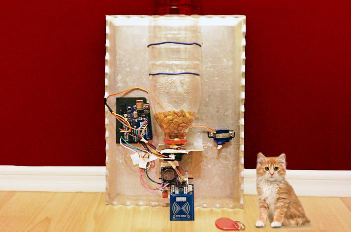
你曾懒得喂你家宠物吗?我们爱我们的宠物,但有时我们也希望能让喂宠物这件事变得自动化一点。今天我们将使用Arduino Uno做一个智能自动宠物喂食器!该项目的主要组件包括一个用来追踪时间、管理喂养计划的RTC模块,一个用来监控食物水平的距离传感器,一个用来区分白天黑夜的光敏传感器,一个用来识别宠物的RFID。好了!让我们开始吧!
硬件
- Arduino Uno
- TEMT6000 光敏传感器
- GP2Y0A21YK 夏普距离传感器
- RFID MFRC522
- 蜂鸣器
- SG90 电机
- RTC DS1307
软件
- Arduino IDE
- https://github.com/todeilatiberia/AutomaticFeeder
工具
- 瓶子(或任何食物容器)
- 金属板 35×25 厘米
第1步:连接光敏传感器
我们使用SparkFun光敏传感器TEMT6000来检测白天和黑夜。之所以需要区分这两者,主要原因是因为我们要确定何时需要投放食物,两次食物投放之间需要间隔多久。TEMT6000光敏传感器有3个引脚:SIG,GND,VCC。将这个传感器接到Arduino板上的步骤非常简单:VCC连接到5V引脚;GND到板上的GND引脚,然后SIG需要接到模拟输入上。我选择了A0引脚。输出引脚SIG的作用就好像一个晶体管,因此在传感器附近的光越亮,引脚输出的电压就越高。
下图显示了TEMT6000感知到的电流和照度之间的关系。照度是总光通量(即光源发出的可见光,以lm为单位)除以面积(m²)的量度。一般来说,1照度(Ix) = 1 / m²。TEMT6000可以识别典型的人类可见光光谱,波长在390-700纳米之间。
TEMT6000技术规格书: https://www.sparkfun.com/datasheets/Sensors/Imaging/TEMT6000.pdf
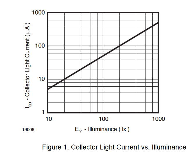
图1:集电极电流vs照度/©Sparkfun
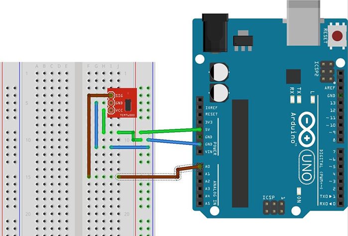
图2:TEMT6000光敏传感器与Arduino Uno的接线图
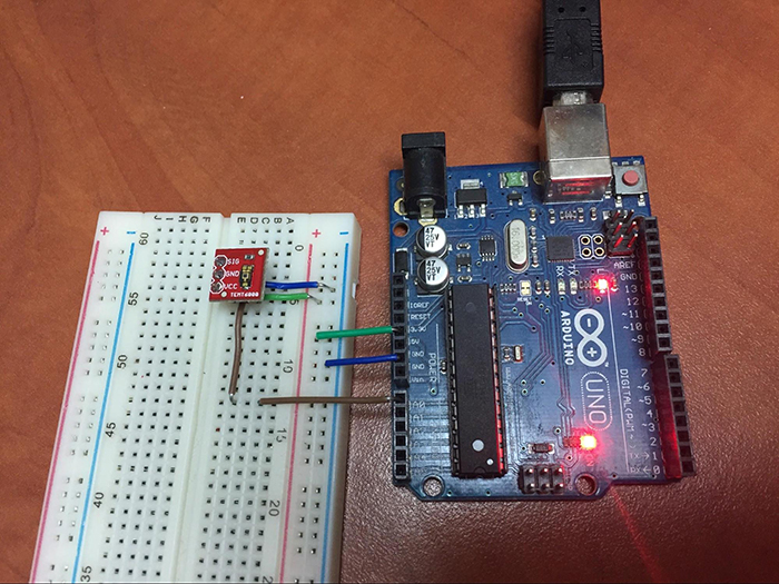
图3:TEMT6000和Arduino Uno之间的接线图
由于该传感器连接在模拟引脚上,而模数转换器的分辨率是10位的,所以其最大值为1023。例如,当传感器接收到来自我手机闪光灯的最亮照射时,从传感器读出的值大约是1023。
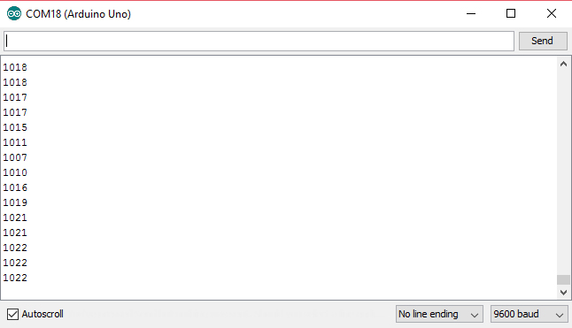
图4:Arduino显示传感器最大值的串口监视器
光敏传感器的代码:
int lightSensor = 0;void setup() { Serial.begin(9600); } void loop() { int valueFromLightSensor = analogRead(lightSensor); Serial.println(valueFromLightSensor); delay(1000); }
复制代码为了测量距离,我选择了一个模拟传感器(Sharp GP2Y0A21YK),因为与其他距离传感器相比,它的效果最好。其工作原理如下:首先发出一个信号,当它发现路上有障碍物时,它也会发回一个信号(一个电压值,该电压值随障碍物的远近而变化),这个电压会转换成距离。
GP2Y0A21YK将被安置在食物容器上方,在开启自动喂食功能前,需要先测量瓶子里的剩余空间(即食物的多少)。有了这个距离传感器,系统将检测食物容器(或瓶子)是满的还是空的。具体工作方式如下:
- 距离较小: 自动系统只会增加一小部分食物;
- 中等距离: 您的宠物将获得一半食物;
- 距离较大: 自动系统将投喂全部食物。
这里的距离表示从安装距离传感器的位置到食品容器底部的距离。由于传感器的量程为10-80 cm,所以传感器需要在食品容器顶部以上10cm处才能读取正确的距离值。
如何确定传感器的最佳拟合线:
摘自 Pololu.com
传感器的输出电压与测量距离的倒数之间的关系在传感器的可用范围内近似线性。您可以使用此图将传感器输出电压转换为一个近似的距离,方法是创建一条最佳拟合线,将输出电压(V)的倒数与距离(cm)联系起来。线性化方程的最简形式可以表述为到反射物体的距离约等于一个常数尺度因子(~ 27v *cm)除以传感器的输出电压之后的数值。因此增加一个恒定的距离偏移量并修改缩放因子可以改善这条线的拟合。
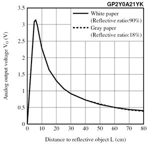
图5:距离传感器的特性 / ©Pololu.com
摘自 Phidgets.com
基于夏普的“典型值”,将传感器值转换为距离的公式(公式仅适用于传感器值在80 – 500之间)为:
距离 (cm) = 4800/(传感器值 – 20)
这种传感器可以找到离物体的距离,这些物体呈现出非常窄的边缘,比如角度非常尖锐的墙壁。
注: 该传感器的输出因单元而异,并取决于目标的特性(反射率、尺寸、运动方向、目标对准)。
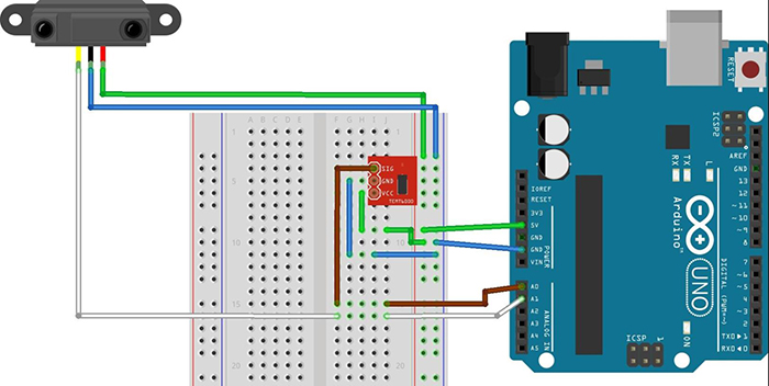
图6:夏普GP2Y0A21YK与Uno之间的接线图
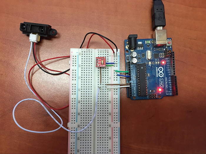
图7:夏普距离传感器、TEMT6000、Uno之间的接线图
代码:
int lightSensor = 0;int distanceSensor=1; void setup() { Serial.begin(9600); } void loop() { int valueFromLightSensor = analogRead(lightSensor); Serial.print("Light Value= "); Serial.print(valueFromLightSensor); Serial.println(""); Serial.print("Distance Value= "); int valueFromDistanceSensor = analogRead(distanceSensor); int distance= 4800/(valueFromDistanceSensor - 20); Serial.print(distance); delay(1000); }
复制代码RTC DS1307模型将被用来确定时间。一个实时的时钟系统承担了确定时间的功能。该电路基于一个频率为32.768 kHz的晶体振荡器展开工作。其原理与手表类似。一个基于晶体振动的机械共振的电子振荡器能产生精确的频率。此频率用来追踪源自计算机的日期和时间。
这是一个实用模块,即使在系统关闭时,上面所配备的电池也能保证系统工作的连续性。
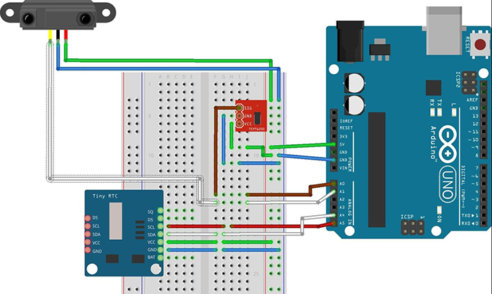
图8:RTC模块接线图
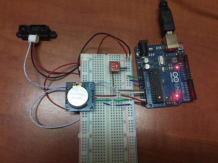
图9:RTC、夏普距离传感器、TEMT6000、Uno之间的接线图
为了获得最佳的使用效果,需要为模块添加两个库。
这两个库可以在我的网址 https://github.com/todeilatiberia/AutomaticFeeder上找到:
- DS1307RTC
- 时间
- 连接线(这个库已经包含在Arduino IDE中,因此添加起来很容易)
找出设置时间:
点击 Arduino IDE → 文件 → 示例 → DS1307RTC → 设置时间
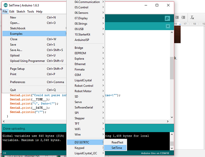
图10:在Arduino IDE上查找设置时间
在图11中,您将看到模块在显示当前日期和时间时正常工作。
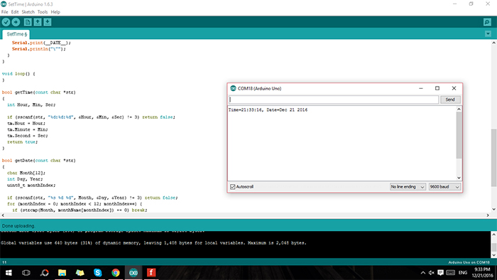
图11: 正确显示当前的日期和时间
在这里,我们将只测量小时的运行情况。为此,我们需要从RTC模块中提取确切的时间。这将通过名为“setSyncProvider(RTC.get)”的RTC简单函数来完成。在实现此功能后,您将能够同时看到串口监视器上的小时数以及距离传感器和光敏传感器上的数值。
代码:
#include <Time.h>#include <Wire.h> #include <DS1307RTC.h> int lightSensor = 0; int distanceSensor=1; void setup() { Serial.begin(9600); setSyncProvider(RTC.get); } void loop() { int valueFromLightSensor = analogRead(lightSensor); Serial.print("Light Value= "); Serial.print(valueFromLightSensor); Serial.println(""); Serial.print("Distance Value= "); int valueFromDistanceSensor = analogRead(distanceSensor); int distance= 4800/(valueFromDistanceSensor - 20); Serial.println(distance); Serial.print("Hour= "); Serial.println(hour()); delay(1000); }
复制代码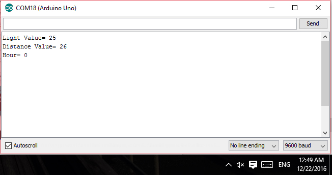
图12:所显示的小时
智能宠物喂食机第2部分—具有语音识别功能的喂食应用程序
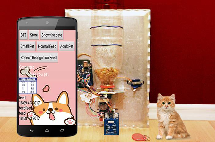
在智能宠物喂食机的第1部分“使用Arduino Uno制作智能自动宠物喂食机”中,我们建立了一个自动化平台,可以判断您的宠物是否被喂食以及计算下一次喂食的时间。在第2部分中,我们将尝试通过MIT App Inventor开发一个应用程序并添加语音识别功能,使系统更加“智能”。在之前的教程中,我们已经使用过MIT App Inventor来创建应用程序。App Inventor是一种易于使用的基于块的语言,用于设计Android应用程序。
硬件
- • Arduino UNO
- • RFID RC522
- • HC-05 蓝牙模块
沿用第1部分的硬件:
- • Arduino Uno
- • 光传感器 TEMT6000
- • 距离传感器 Sharp GP2Y0A21YK
- • RFID RC522
- • 蜂鸣器
- • 电机 SG90
- • RTC DS1307
软件
- Arduino IDE
- GitHub上的PetFeeder
- MIT App Inventor
步骤1:使用带有RFID标签的EEPROM
我们在第1部分中设置的用于EEPROM的标签—在该存储器中,标签将被保存到我们将其清除为止。此功能有助于我们将自己的宠物与其他宠物分开来,只为带有指定标签的宠物提供食物。
我们在第1部分中设置了两个标签,并使用EEPROM来存储数据。RFID标签有助于识别您的宠物并将其与其他人的宠物区分开,从而仅向带有指定标签的宠物提供食物。使用EEPROM可以确保数据在系统重新启动后也可以安全地存储在内存中。您可以使用以下代码从EEPROM更改标签信息:
#include <EEPROM.h> #include <SPI.h> #include <MFRC522.h> boolean match = false; boolean programMode = false; int isOurPet; byte storedCard[4]; byte readCard[4]; byte masterCard[4]; #define SS_PIN 10 #define RST_PIN 9 MFRC522 mfrc522(SS_PIN, RST_PIN); void setup() { Serial.begin(9600); SPI.begin(); mfrc522.PCD_Init(); if (EEPROM.read(1) != 143) { do { isOurPet = findOurPet(); } while (!isOurPet); for ( int j = 0; j < 4; j++ ) { EEPROM.write( 2 + j, readCard[j] ); } EEPROM.write(1, 143); } for ( int i = 0; i < 4; i++ ) { masterCard[i] = EEPROM.read(2 + i); } } void loop () { do { isOurPet = findOurPet(); } while (!isOurPet); if ( master(readCard)) { programMode = true; Serial.println(F("Our Pet - Green Tag")); int count = EEPROM.read(0); } else { Serial.println(F("Not our pet - Purple Tag")); } } int findOurPet() { if ( ! mfrc522.PICC_IsNewCardPresent()) { return 0; } if ( ! mfrc522.PICC_ReadCardSerial()) { return 0; } for (int i = 0; i < 4; i++) { readCard[i] = mfrc522.uid.uidByte[i]; } mfrc522.PICC_HaltA(); // Stop reading return 1; } void readCollar( int number ) { int start = (number * 4 ) + 2; for ( int i = 0; i < 4; i++ ) { storedCard[i] = EEPROM.read(start + i); } } boolean EEpromCheck ( byte a[], byte b[] ) { if ( a[0] != NULL ) match = true; for ( int k = 0; k < 4; k++ ) { if ( a[k] != b[k] ) match = false; } if ( match ) { return true; } else { return false; } } boolean master( byte test[] ) { if ( EEpromCheck( test, masterCard ) ) return true; else return false; }
复制代码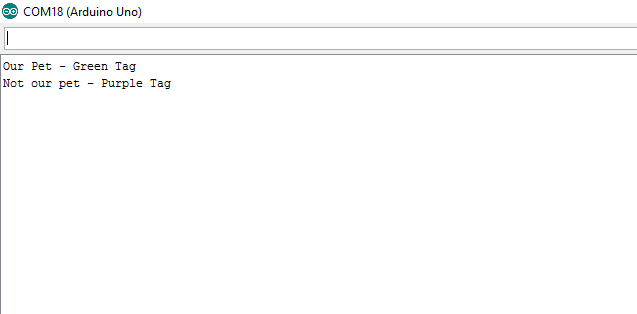
图1:我们在EEPROM中的宠物标签
上次,我们将宠物指定为红色标签。这次,我们将标签更改为绿色。
步骤2:怎样控制伺服
伺服电机通过来自微控制器的PWM(脉冲宽度调节)来更改其位置。伺服需要进行校准,并将其阀门开度角度设置为90度。
为了控制伺服,我们将使用ArduinoSweep 代码。该代码中伺服电机轴可以旋转180度。我们将把旋转角度从0-180度更改为10-170度。
#include <Servo.h>Servo myservo; // create servo object to control a servo int pos = 0; // variable to store the servo position void setup() { myservo.attach(9); // attaches the servo on pin 9 to the servo object } void loop() { for(pos = 10; pos <= 170; pos += 1) // goes from 10 degrees to 170 degrees // in steps of 1 degree { myservo.write(pos); // tell servo to go to position in variable ‘pos’ delay(15); // waits 15ms for the servo to reach the position } for(pos = 170; pos>=10; pos -= 1) // goes from 170 degrees to 10 degrees { myservo.write(pos); // tell servo to go to position in variable ‘pos’ delay(15); // waits 15ms for the servo to reach the position } }
复制代码您的伺服在某些时候可能会行为异常。当您由于Arduino自行重启而无法执行指令时,可能是因为USB端口没有提供足够的电源来驱动伺服。在这种情况下,Arduino会进行重置,应用程序也无法工作。用以下两种方法可以避免此问题的产生:
- 1. 您可以在面包板上的GND和5V之间添加一个大容值电容器(470uF或更大)。当Arduino没有足够的电源来维持电流时,该电容器可以用作临时电源。较长的端子必须连接到VDD=5V,而较短的端子必须连接到GND。
- 2. 您可以通过USB对开发板进行编程,之后断开连接。然后,您可以使用手机充电器通过插头来为装置供电,因为它具有更大的电流容量。
让我们简要地看一下<Servo.h> 库的工作方式。
#include <Servo.h>
必须含有该指令才能使用Servo.h库。Servo库中给出的两个示例是“Knob”和“Sweep”。这两个控件对伺服的测试很有用。使用Knob,您就可以通过电位计将伺服转动到特定角度。使用Sweep,您就可以在180度的范围内来回扫动伺服轴。
Servo servo;
这是一个类型的声明。它定义了servo类型的变量Servo。它与其他用于伺服的类型相似,如int(整型)和float(浮点型)。
servo.attach(servoPin);
在设置代码块时,您需要将伺服分配给特定的引脚。该指令用于将伺服变量分配引脚。
servo.write(angle);
此指令将设置伺服轴角度(在0到180度范围内),然后将伺服转动至该角度。
步骤3:添加HC-05蓝牙模块
———-
关于蓝牙HC-05 – 用户使用手册
蓝牙串行模块的运行不需要进行驱动,并且可以与具有串行接口的其他蓝牙设备进行通信。两个蓝牙模块之间实现通信至少需要两个条件:
(1) 必须在主设备和从设备之间进行。
(2) 密码必须正确。
该模块的属性:
- • 可以在主模式和从模式之间切换
- • 蓝牙名称: HC-05
- • 密码: 1234
配对:主设备不仅可以与指定的蓝牙地址配对(如手机、计算机适配器、从设备),还可以自动搜索从设备并与之配对。
典型方法:在某些特定条件下,主设备和从设备可以自动配对(这是默认方法)。
———-
在本项目中,我们选择了蓝牙连接,因为这种方式易于配置。蓝牙模块用作Arduino的串行端子,将被连接到TX和RX引脚。
想要通过蓝牙进行数据传输需要遵循一些规则。我们需要有:
- • (通常值为逻辑0)
- • 数据位
- • 校验位(数据位的和;我们将会比较从头到尾所有位的和)
- • 停止位(大多数情况下值为逻辑1)
引脚连接:
- 1.将HC-05的TX引脚连接到Arduino的RX引脚。
- 2.将HC-05的RX引脚连接到Arduino的TX引脚。
- 3.将GND引脚连接在一起。
在我们之前的教程制作您自己的Arduino RFID门锁—第2部分:用智能手机解锁中对HC-05设置进行了详细说明。如果您在连接蓝牙模块时遇到问题,请参考上述教程。
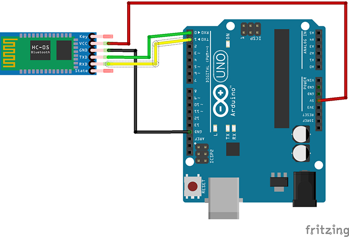
图2:HC-05和Arduino Uno之间的连接
蓝牙传输代码:
该程序还将比较来自“voice(声音)”变量的字符串和串口读取的字符串。如果两者相同,则会向电机发送一个指令来触发SG90伺服电机。
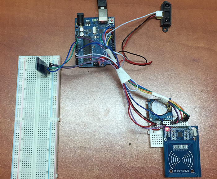
图3:连接到第1部分装置中的HC-05蓝牙模块
步骤3:设计应用程序
现在,让我们来创建一个应用程序吧!和以前一样,我们将使用MIT App Inventor。我们的最终目标是创建一个对所连接的多种设备进行集成的组合型应用程序(例如,集成了多个所连接设备的智能家居应用程序)。
有关MIT App Inventor的设置指南,请参考上一教程制作您自己的Arduino RFID门锁—第2部分:用智能手机解锁 (步骤3:应用程序)。本教程将分步指导您使用App Inventor创建自己的应用程序。
我们所创建的应用程序将会具有一个简单的界面,其中包含以下功能:
- • 连接到蓝牙
- • 使您可以远程喂食宠物
- • 存储:将数据(以文件形式)存储在手机中
- • 显示日期:在手机屏幕上显示日期信息
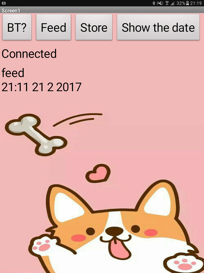
图4:宠物喂食器应用程序的简单用户界面
该程序的模块图非常简单易懂:
- •第一个模块:第一个模块用于蓝牙按钮
- • ListPicker – MIT App Inventor单击该按钮,将显示文本列表供用户选择。可以通过Designer或Blocks Editor来指定文本内容,方法是将ElementsFromString属性设置为文本的拆分字符串级联(例如,选择1,选择2,选择3)或者将Elements属性设置为一个Blocks editor中的列表。
- • ListPicker – MIT App Inventor单击该按钮,将显示文本列表供用户选择。可以通过Designer或Blocks Editor来指定文本内容,方法是将ElementsFromString属性设置为文本的拆分字符串级联(例如,选择1,选择2,选择3)或者将Elements属性设置为一个Blocks editor中的列表。
- • ListPicker 显示所有可用的蓝牙;该功能在您选择某一个蓝牙前有效。

图5:第一个模块
- • 第二个模块:通过调用BluetoothClient1.Connect address现应用程序与客户端之间的连接。您手机中的蓝牙将搜索附近的设备,并将其显示在ListPicker中。您可以选择要配对的设备。

图6:第二个模块
同时还有一个标签,在建立连接后标签上会显示相关消息。如果设备已经成功连接,您将在屏幕上看到“已连接(Connected)”的消息。
- • 第三个模块:仅用于连接完成时通过客户端发送一个消息。该文本以串行通信的方式,通过蓝牙从一个设备发送到另一个设备。这就像在Arduino的串行监视器中键入文本一样。
当我们从串行读取数据时,就是在对用户的输入与Arduino内存中存储的字符串进行比较。这就是算法的工作原理。

图7:第三个模块
我们接下来看看另一组模块图:
- • 第一个模块:将蓝牙传输的日期保存到存储在手机内存里的.txt文件中。

图8:第一个模块
- • 第二个模块:当按下按钮时,将会读取保存在文本文件中的数据。

图9:第二个模块
- • 第三个模块:将喂食的时间和标签写入屏幕。这个信息很有用,因为它可以帮助我们对喂食时间进行记录,如果我们不想对宠物喂食过多,可以查看时间来确认。

图10:第三个模块
- • 第四个模块:发生错误时,该模块将删除.txt文件中的所有数据。这一功能很重要,因为一旦执行,将不再显示以前的信息。

图11:第四个模块
该应用程序的第二部分提供了不同的喂食模式:正常喂食模式,用于宠物宝宝的喂食模式和用于成年宠物的喂食模式。这也为您提供了需要为宠物喂食多少食物量的有关信息。其中最酷的功能之一是语音识别模式。我们将在下文中讨论有关该功能的更多内容。
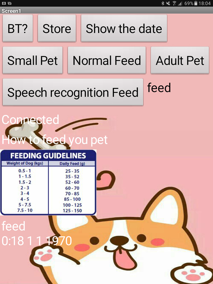
图12:应用程序上显示的非正确时间和日期
如果想要查找喂食的日期和时间,可以按“显示日期”按钮。该应用程序是以精简模式制作的,因为并不是每个人都希望看到所有信息。如图所示,日期和时间显示不正确。为了获得确切的日期和时间,我们需要使用Arduino IDE中的Set Time 示例。现在,RTC模块将指示正确的日期和时间。
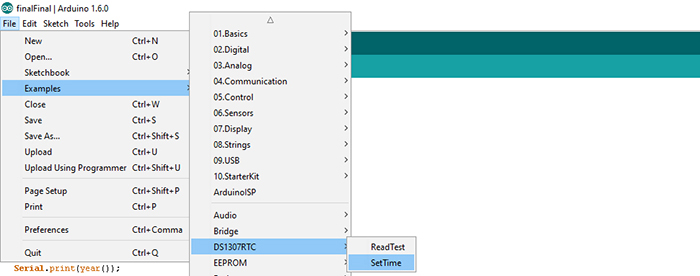
图13:如何找到Arduino IDE中的SetTime
Set Time code:#include <Wire.h> #include <TimeLib.h> #include <DS1307RTC.h> const char *monthName[12] = { "Jan", "Feb", "Mar", "Apr", "May", "Jun", "Jul", "Aug", "Sep", "Oct", "Nov", "Dec" }; tmElements_t tm; void setup() { bool parse=false; bool config=false; // get the date and time the compiler was run if (getDate(__DATE__) && getTime(__TIME__)) { parse = true; // and configure the RTC with this info if (RTC.write(tm)) { config = true; } } Serial.begin(9600); while (!Serial) ; // wait for Arduino Serial Monitor delay(200); if (parse && config) { Serial.print("DS1307 configured Time="); Serial.print(__TIME__); Serial.print(", Date="); Serial.println(__DATE__); } else if (parse) { Serial.println("DS1307 Communication Error :-{"); Serial.println("Please check your circuitry"); } else { Serial.print("Could not parse info from the compiler, Time=""); Serial.print(__TIME__); Serial.print("", Date=""); Serial.print(__DATE__); Serial.println("""); } } void loop() { } bool getTime(const char *str) { int Hour, Min, Sec; if (sscanf(str, "%d:%d:%d", &Hour, &Min, &Sec) != 3) return false; tm.Hour = Hour; tm.Minute = Min; tm.Second = Sec; return true; } bool getDate(const char *str) { char Month[12]; int Day, Year; uint8_t monthIndex; if (sscanf(str, "%s %d %d", Month, &Day, &Year) != 3) return false; for (monthIndex = 0; monthIndex < 12; monthIndex++) { if (strcmp(Month, monthName[monthIndex]) == 0) break; } if (monthIndex >= 12) return false; tm.Day = Day; tm.Month = monthIndex + 1; tm.Year = CalendarYrToTm(Year); return true; }
复制代码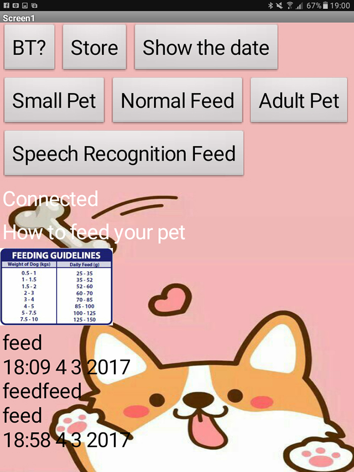
图14:应用程序的最终版本
应用程序概述:
- • 需要连接到蓝牙。
- • 根据宠物的年龄采用不同的喂食模式。
- • 要激活语音识别模式,只需单击“语音识别喂食”按钮并讲话即可。
- • 仅当正确说出指令时,喂食器才能运行。如果关键字不正确(无法正确识别),则只会在标签上显示而不执行指令。
- • 在语音识别的模式下,当两次说出/重复“喂食”指令(比如您没有等待几秒钟的时间让系统对信息进行处理)时,指令就会变成“喂食喂食”,这不是有效的指令。它将保留在标签上而不执行。
- • 如果语音识别上的“喂食”指令正常工作,标签上将会打印出时间。
- • 仅当正确说出指令时,喂食器才能运行。如果关键字不正确(无法正确识别),则只会在标签上显示而不执行指令。
- • 还包括一个喂食指南,您可以根据宠物的体重查找有关所应提供食物量的信息。
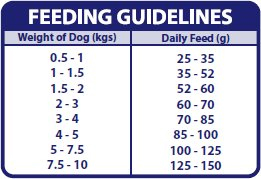
图15:宠物喂食指南/ ©Fish4Dogs
所有指令都可以在Arduino IDE的串行监视器上找到。这有助于我们在必要时对应用程序进行调试。
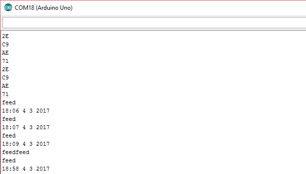
图16:串行监视器中显示的喂食数据
对于语音识别,我们需要一个按钮来激活该模式。我们可以使用App Inventor中已经提供的SpeechRecognizer组件。
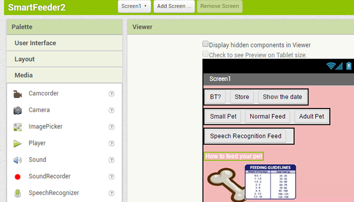
图17:在MIT App Interventor上添加SpeechRecognizer组件
有了这两个组件后,将它们连接起来非常简单。您需要处理来自讲话者的文本。这是通过调用SpeechRecognizer.GetText来完成的。之后,您需要有一个标签来显示所说的内容,也可以没有这个标签,但是如果没有标签您将无法看到自己是否说了正确的指令。在程序循环中,您还需要通过蓝牙将语音指令传输到Arduino,需要使用SentText text程序。
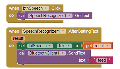
图18:语音识别模块
对于每种模式,您都需要有相对应的按钮。每个按钮对应不同的指令,该指令将会被发送到Arduino,然后据此喂食不同量的食物。


图19:宠物宝宝模式,正常喂食模式和成年宠物模式模块
来源:techclass.rohm


 /7
/7 


