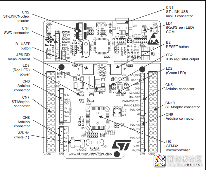
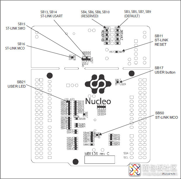
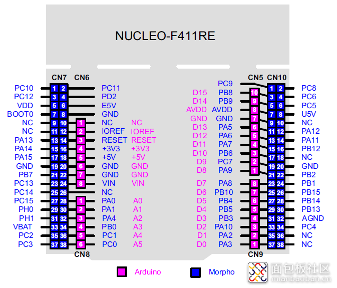
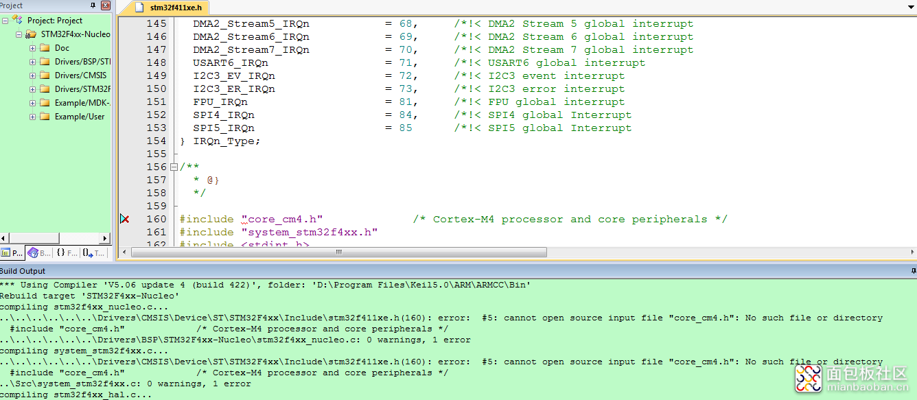
接着让我们聊聊搭建软件环境中需要注意的事项。首次安装好MDK后需要将其破解,想必大伙这都很清楚,如果没有将其破解,编译的时候就会报一些莫名其妙的错误。然后要下载自己所使用开发板的PACK包,如“Keil.STM32F4xx_DFP.2.13.0.pack”,这可以通过Keil在线安装也可以选择离线导入的方式。安装好PACK包,新建工程时才会在选择芯片型号的界面显示出对应的芯片选项。打开官方的示例,所在路径最好不要包含中文字样,否则编译也会出现莫名其妙的错误。直接编译原始工程,结果会报很多问题,如下图所示。官方的源码中没有包含“core_cm4.h”头文件,需要我们手动添加,可以拷贝其它STM32工程中的,也可在选项卡中设置包含安装好pack包路径下core_cm4.h所在的文件夹或者微控制器软件接口标准(CMSIS)中所含core_cm4.h对应的文件夹。
然后编译完成后,我们将可执行文件通过ST-LINK烧录进flash时,又会报不是ARMCortex™-M4的程序,找不到相应的device配置,然后打开烧录“Cortex-M Target Driver Setup”下的Flash Download,去执行“Add"的时候没有找到我们所对应的STMF411选项,这是因为我们没有安装MDK v4 Legacy Support包,需要在网上下载对应的包,安装后才可以看到更多芯片型号的信息列表。其下载路径:http://www2.keil.com/mdk5/legacy/,如下图所示:

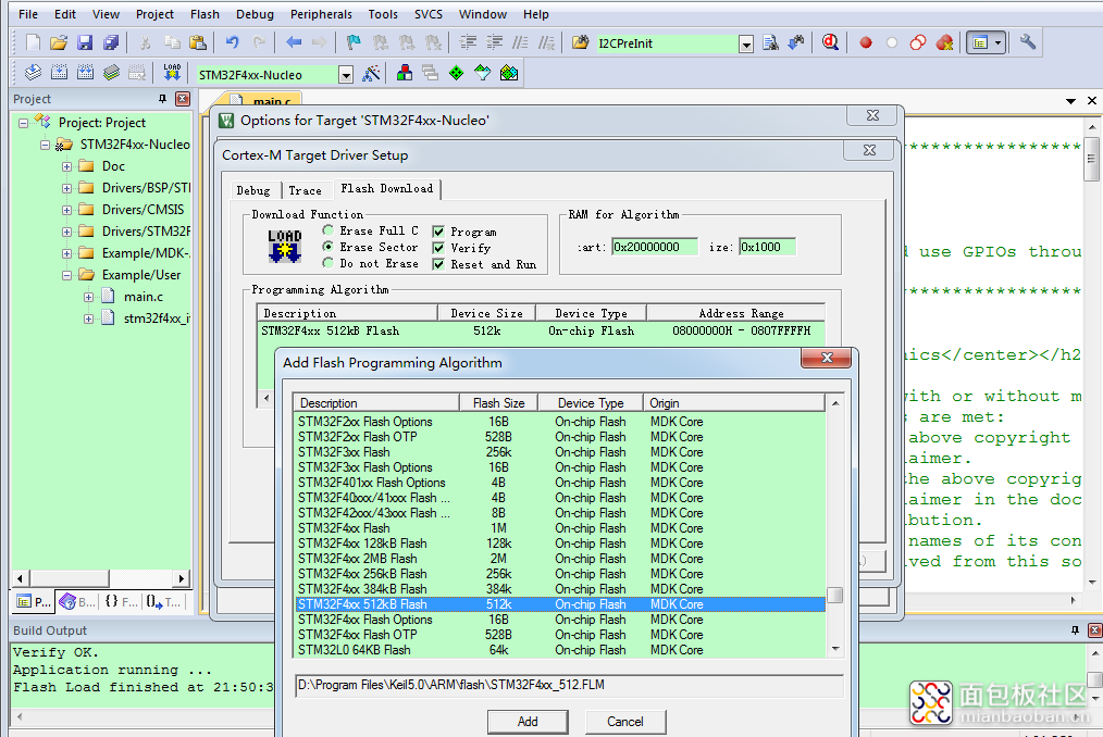
然后可以顺利地将编译好的程序烧录进开发板中运行了。
部分代码如下:
HAL_StatusTypeDef HAL_Init(void){ /* Configure Flash prefetch, Instruction cache, Data cache */ #if (INSTRUCTION_CACHE_ENABLE != 0) __HAL_FLASH_INSTRUCTION_CACHE_ENABLE(); #endif /* INSTRUCTION_CACHE_ENABLE */ #if (DATA_CACHE_ENABLE != 0) __HAL_FLASH_DATA_CACHE_ENABLE(); #endif /* DATA_CACHE_ENABLE */ #if (PREFETCH_ENABLE != 0) __HAL_FLASH_PREFETCH_BUFFER_ENABLE(); #endif /* PREFETCH_ENABLE */ /* Set Interrupt Group Priority */ HAL_NVIC_SetPriorityGrouping(NVIC_PRIORITYGROUP_4); /* Use systick as time base source and configure 1ms tick (default clock after Reset is HSI) */ HAL_InitTick(TICK_INT_PRIORITY); /* Init the low level hardware */ HAL_MspInit(); /* Return function status */ return HAL_OK; }
复制代码/** * @brief System Clock Configuration * The system Clock is configured as follow : * System Clock source = PLL (HSI) * SYSCLK(Hz) = 100000000 * HCLK(Hz) = 100000000 * AHB Prescaler = 1 * APB1 Prescaler = 2 * APB2 Prescaler = 1 * HSI Frequency(Hz) = 16000000 * PLL_M = 16 * PLL_N = 400 * PLL_P = 4 * PLL_Q = 7 * VDD(V) = 3.3 * Main regulator output voltage = Scale2 mode * Flash Latency(WS) = 3 * @param None * @retval None */ static void SystemClock_Config(void) { RCC_ClkInitTypeDef RCC_ClkInitStruct; RCC_OscInitTypeDef RCC_OscInitStruct; /* Enable Power Control clock */ __PWR_CLK_ENABLE(); /* The voltage scaling allows optimizing the power consumption when the device is clocked below the maximum system frequency, to update the voltage scaling value regarding system frequency refer to product datasheet. */ __HAL_PWR_VOLTAGESCALING_CONFIG(PWR_REGULATOR_VOLTAGE_SCALE1); /* Enable HSI Oscillator and activate PLL with HSI as source */ RCC_OscInitStruct.OscillatorType = RCC_OSCILLATORTYPE_HSI; RCC_OscInitStruct.HSIState = RCC_HSI_ON; RCC_OscInitStruct.HSICalibrationValue = 0x10; RCC_OscInitStruct.PLL.PLLState = RCC_PLL_ON; RCC_OscInitStruct.PLL.PLLSource = RCC_PLLSOURCE_HSI; RCC_OscInitStruct.PLL.PLLM = 16; RCC_OscInitStruct.PLL.PLLN = 400; RCC_OscInitStruct.PLL.PLLP = RCC_PLLP_DIV4; RCC_OscInitStruct.PLL.PLLQ = 7; if(HAL_RCC_OscConfig(&RCC_OscInitStruct) != HAL_OK) { Error_Handler(); } /* Select PLL as system clock source and configure the HCLK, PCLK1 and PCLK2 clocks dividers */ RCC_ClkInitStruct.ClockType = (RCC_CLOCKTYPE_SYSCLK | RCC_CLOCKTYPE_HCLK | RCC_CLOCKTYPE_PCLK1 | RCC_CLOCKTYPE_PCLK2); RCC_ClkInitStruct.SYSCLKSource = RCC_SYSCLKSOURCE_PLLCLK; RCC_ClkInitStruct.AHBCLKDivider = RCC_SYSCLK_DIV1; RCC_ClkInitStruct.APB1CLKDivider = RCC_HCLK_DIV2; RCC_ClkInitStruct.APB2CLKDivider = RCC_HCLK_DIV1; if(HAL_RCC_ClockConfig(&RCC_ClkInitStruct, FLASH_LATENCY_3) != HAL_OK) { Error_Handler(); } }
复制代码int main(void){ /* STM32F4xx HAL library initialization: - Configure the Flash prefetch, instruction and Data caches - Configure the Systick to generate an interrupt each 1 msec - Set NVIC Group Priority to 4 - Global MSP (MCU Support Package) initialization */ HAL_Init(); /* Configure the system clock to 100 Mhz */ SystemClock_Config(); /*##-1- Enable GPIOA Clock (to be able to program the configuration registers) */ __GPIOA_CLK_ENABLE(); /*##-2- Configure PA05 IO in output push-pull mode to drive external LED ###*/ GPIO_InitStruct.Pin = GPIO_PIN_5; GPIO_InitStruct.Mode = GPIO_MODE_OUTPUT_PP; GPIO_InitStruct.Pull = GPIO_PULLUP; GPIO_InitStruct.Speed = GPIO_SPEED_FAST; HAL_GPIO_Init(GPIOA, &GPIO_InitStruct); /*##-3- Toggle PA05 IO in an infinite loop ##*/ while (1) { HAL_GPIO_TogglePin(GPIOA, GPIO_PIN_5); /* Insert delay 100 ms */ HAL_Delay(100); // HAL_GPIO_TogglePin(GPIOA, GPIO_PIN_5); // /* Insert delay 200 ms */ // HAL_Delay(200); } }
复制代码本次使用评测就到这里吧,后续将I2C的OLED屏相关代码添加进来,实现汉字显示,bmp图片点亮OLED屏。尽请期待,当然是在有时间的前提下。谢谢各位!再次感谢社区举办的活动!


 /5
/5 

