本文档概述了一种基于 SCI/UART 输入信号,可以自动校准本设备SCI/UART波特率的方法,该方法适用与所有第三代C2000芯片,比如F2807x/37x,F28004x,F28002x等等。
一 原理说明
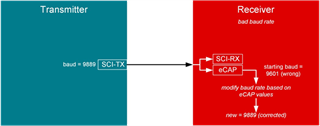
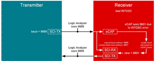
假设有2块电路板通过SCI进行通信。“Transmitter”向“Receiver”发送未知波特率的数据,“ Receiver”则使用 eCAP 测量未知的波特率,然后修改其自身的波特率和“Transmitter”匹配。
下面款图是一种情况,其中“Transmitter” 的波特率设置为 9889,而“Receiver”的初始波特率设置为 9601 ,相比之下“Receiver”的波特率为 -3% 偏差。 经过算法的自动校准以后,“Receiver”将会把自身波特率校正为与“Transmitter”相同的9889。


二 Receiver 的校准代码
1. 初始化
需要配置以下模块来校准波特率:- 时钟:使用 INTOSC2 并选择 100MHz 的 LSPCLK
#define DEVICE_SETCLOCK_CFG (SYSCTL_OSCSRC_OSC2 | SYSCTL_IMULT(20) | \ SYSCTL_FMULT_NONE | SYSCTL_SYSDIV(2) | \ SYSCTL_PLL_ENABLE) // // Set up PLL control and clock dividers // SysCtl_setClock(DEVICE_SETCLOCK_CFG); // // Make sure the LSPCLK divider is set to the default (divide by 4) // SysCtl_setLowSpeedClock(SYSCTL_LSPCLK_PRESCALE_1);
复制代码- SCI 模块:通讯数据使用,发出校准以后的波形
// Initialize SCIA and its FIFO. // SCI_performSoftwareReset(SCIA_BASE); // // Configure SCIA for communications. // SCI_setConfig(SCIA_BASE, DEVICE_LSPCLK_FREQ, TARGETBAUD, (SCI_CONFIG_WLEN_8 | SCI_CONFIG_STOP_ONE | SCI_CONFIG_PAR_NONE)); SCI_resetChannels(SCIA_BASE); SCI_resetRxFIFO(SCIA_BASE); SCI_resetTxFIFO(SCIA_BASE); SCI_clearInterruptStatus(SCIA_BASE, SCI_INT_TXFF | SCI_INT_RXFF); SCI_enableFIFO(SCIA_BASE); SCI_enableModule(SCIA_BASE); SCI_performSoftwareReset(SCIA_BASE);
复制代码- Xbar 输入:将 GPIO28/SCI 内部连接到 INPUTXBAR7 与 ECAP1 配合使用
// // Configure GPIO 28 as eCAP input // XBAR_setInputPin(XBAR_INPUT7, 28);
复制代码- ECAP 模块:监控接收到的 SCI 通信脉冲宽度
// // Disable ,clear all capture flags and interrupts // ECAP_disableInterrupt(ECAP1_BASE, (ECAP_ISR_SOURCE_CAPTURE_EVENT_1 | ECAP_ISR_SOURCE_CAPTURE_EVENT_2 | ECAP_ISR_SOURCE_CAPTURE_EVENT_3 | ECAP_ISR_SOURCE_CAPTURE_EVENT_4 | ECAP_ISR_SOURCE_COUNTER_OVERFLOW | ECAP_ISR_SOURCE_COUNTER_PERIOD | ECAP_ISR_SOURCE_COUNTER_COMPARE)); ECAP_clearInterrupt(ECAP1_BASE, (ECAP_ISR_SOURCE_CAPTURE_EVENT_1 | ECAP_ISR_SOURCE_CAPTURE_EVENT_2 | ECAP_ISR_SOURCE_CAPTURE_EVENT_3 | ECAP_ISR_SOURCE_CAPTURE_EVENT_4 | ECAP_ISR_SOURCE_COUNTER_OVERFLOW | ECAP_ISR_SOURCE_COUNTER_PERIOD | ECAP_ISR_SOURCE_COUNTER_COMPARE)); // // Disable CAP1-CAP4 register loads // ECAP_disableTimeStampCapture(ECAP1_BASE); // // Configure eCAP // Enable capture mode. // One shot mode, stop capture at event 4. // Set polarity of the events to rising, falling, rising, falling edge. // Set capture in time difference mode. // Select input from XBAR7. // Enable eCAP module. // Enable interrupt. // ECAP_stopCounter(ECAP1_BASE); ECAP_enableCaptureMode(ECAP1_BASE); ECAP_setCaptureMode(ECAP1_BASE, ECAP_ONE_SHOT_CAPTURE_MODE, ECAP_EVENT_4); ECAP_setEventPolarity(ECAP1_BASE, ECAP_EVENT_1, ECAP_EVNT_FALLING_EDGE); ECAP_setEventPolarity(ECAP1_BASE, ECAP_EVENT_2, ECAP_EVNT_RISING_EDGE); ECAP_setEventPolarity(ECAP1_BASE, ECAP_EVENT_3, ECAP_EVNT_FALLING_EDGE); ECAP_setEventPolarity(ECAP1_BASE, ECAP_EVENT_4, ECAP_EVNT_RISING_EDGE); ECAP_enableCounterResetOnEvent(ECAP1_BASE, ECAP_EVENT_1); ECAP_enableCounterResetOnEvent(ECAP1_BASE, ECAP_EVENT_2); ECAP_enableCounterResetOnEvent(ECAP1_BASE, ECAP_EVENT_3); ECAP_enableCounterResetOnEvent(ECAP1_BASE, ECAP_EVENT_4); ECAP_selectECAPInput(ECAP1_BASE, ECAP_INPUT_INPUTXBAR7); ECAP_enableLoadCounter(ECAP1_BASE); ECAP_setSyncOutMode(ECAP1_BASE, ECAP_SYNC_OUT_DISABLED); ECAP_startCounter(ECAP1_BASE); ECAP_enableTimeStampCapture(ECAP1_BASE); ECAP_reArm(ECAP1_BASE); ECAP_enableInterrupt(ECAP1_BASE, ECAP_ISR_SOURCE_CAPTURE_EVENT_4);
复制代码捕获传入 SCI 通信的脉冲宽度,每捕获 4 次就中断一次。 将这 4 个捕获添加到阵列中。
__interrupt void ecap1ISR(void){ if(stopCaptures==0) { // // Get the capture counts, interrupt every 4. Can be 1-bit or more wide. // add one to account for partial eCAP counts at higher baud rates // (e.g. count = 40, but if had higher resolution, this would be 40.5) // capCountArr[0] = 1+ECAP_getEventTimeStamp(ECAP1_BASE, ECAP_EVENT_1); capCountArr[1] = 1+ECAP_getEventTimeStamp(ECAP1_BASE, ECAP_EVENT_2); capCountArr[2] = 1+ECAP_getEventTimeStamp(ECAP1_BASE, ECAP_EVENT_3); capCountArr[3] = 1+ECAP_getEventTimeStamp(ECAP1_BASE, ECAP_EVENT_4); // // Add samples to a buffer. Get average baud and tune INTOSC if buffer filled. // capCountIter = 0; for (capCountIter=0; capCountIter<4; capCountIter++) { // // if we still have samples left to capture, add it to the samples array // if(samplesArrIter<NUMSAMPLES) { samplesArr[samplesArrIter] = capCountArr[capCountIter]; samplesArrIter++; } // // else, all samples were received, break to begin tuning // else { stopCaptures=1; break; } } } // // Clear interrupt flags for more interrupts. // ECAP_clearInterrupt(ECAP1_BASE,ECAP_ISR_SOURCE_CAPTURE_EVENT_4); ECAP_clearGlobalInterrupt(ECAP1_BASE); // // Start eCAP // ECAP_reArm(ECAP1_BASE); // // Acknowledge the group interrupt for more interrupts. // Interrupt_clearACKGroup(INTERRUPT_ACK_GROUP4); }
复制代码捕获阵列满后,计算阵列的平均脉冲宽度 (也就是波特率),并更新SCI波特率寄存器,使其尽可能接近计算的平均值。
// // Loop forever. Suspend or place breakpoints to observe the buffers. // for(;;) { // // Array is filled, begin tuning // if(stopCaptures==1) { // // Get an average baud rate from the array of samples // uint32_t avgBaud = getAverageBaud(samplesArr,NUMSAMPLES,TARGETBAUD); // // if the baud function returns the error code '0', then flag an error // if(avgBaud==0) { ESTOP0; } // // Update the device's baud rate to match the measured baud rate // SCI_setBaud(SCIA_BASE, DEVICE_LSPCLK_FREQ, avgBaud); // // (OPTIONAL) Continuously send data to SCITX once tuning // is complete for external observation (by logic analyzer or scope) // //unsigned char *msg; //while(1) //{ // msg = "aaaaaaaaaaaaaaaaaaaaaaaaaaaaaaaaaaaaaaaaaaaaaaaaaaaaaaaaaaaaaaaaaaaaaaaaaaaaaaaaaaaaaaaaaa\0"; // SCI_writeCharArray(SCIA_BASE, (uint16_t*)msg, 91); //} // // Wait for user to view the results in "Expressions" window // ESTOP0; // // If continuing, reset the array iterator and unlock the ISR for new captures // samplesArrIter=0; stopCaptures=0; } }
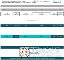
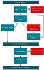
复制代码对于许多应用的SCI 通信,传输的数据 (例如 0xA5)是变化不固定的,因此SCI的高低电平脉冲宽度就是变化的。所以必须对样本阵列进行如下的预处理,然后才能计算平均脉冲宽度。
a) 丢弃大于 10 位宽的脉冲宽度 (丢弃空闲时间)
b) 将 n 位值除以 n
c) 对修改后的样本数组进行平均化
uint32_t getAverageBaud(volatile float arr[], int size, float targetBaudRate){ // // clean up variable width array to single-bit-width array // uint16_t pass = arrTo1PulseWidth(arr, size, (float)DEVICE_SYSCLK_FREQ/targetBaudRate); // // pass only if enough good samples provided // if(pass == 0) { return 0; } // // convert 2-bit width, 3-bit width, etc. to 1-bit width values by dividing, and average these values. // skip unrelated values // float averageBitWidth = computeAvgWidth(arr, size); // // get the rounded baud rate from the average number of clocks and the sysclk frequency // return (uint32_t)(((float)DEVICE_SYSCLK_FREQ/(float)averageBitWidth)+0.5); }
复制代码

三 结果
按照以下设置进行测试,结果详见表格,校准以后的误差从3% 改善为0.1%左右甚至更小。
- “Transmitter”设置为正确的波特率 (我们尝试匹配的波特率)
- “Receiver”设置为错误波特率 (-3% 或 +3%)
- “Receiver”运行校准程序以匹配“Transmitter”
| 100K 波特率 | 9601波特率 | ||||
| -3% | +3% | -3% | +3% | ||
| Transmitter (我们正在尝试匹配的内容) | 理想波特率 (仅供参考) | 103306 | 96899 | 9889 | 9314. |
| 实际波特率 (必须与此匹配) | 104174. | 96906 | 9890 | 9315. | |
| Receiver (初始错误波特率) | 波特率 (校准前) | 100154. | 100157. | 9622. | 9622. |
| 出错百分比 (校准前) | -3.859% | 3.355% | -2.706% | 3.296% | |
| Receiver (校准后波特率) | 波特率 (校准后) | 104336. | 97047. | 9888 | 9314. |
| 出错百分比 (校准后) | 0.156% | 0.146% | -0.016% | -0.012% | |
来源:TI


 /1
/1 

