很高兴能得到测评CPK-RA6M4评估板的机会,初见时就产生一种厚重感,原来不但寄来了开发板和USB数据线,还寄来了2本使用的资料,这在以往是较少出现的。
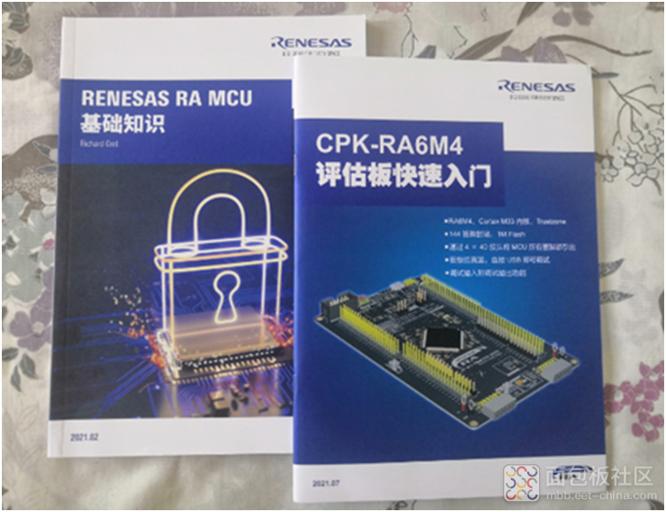
图1 产品资料
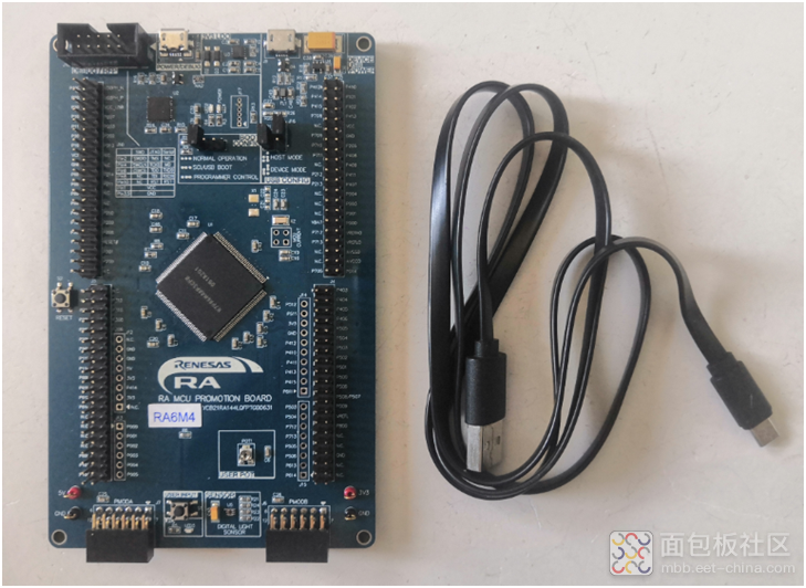
图2 开发工具
粗略地上电测试了一下,基本上就是红色的LED灯在闪烁,似乎并没有其它的现象。
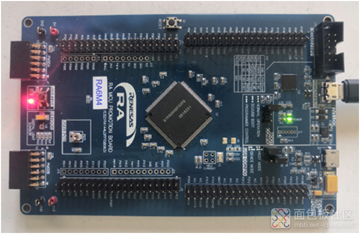
图3 上电效果
为了能更深入地进行测评,接下来的工作就是为其搭建一个开发环境。就CPK-RA6M4评估板来讲,厂家推荐的开发工具是e2 studio,但本人对它实在是不感兴趣。好在RT-T还是支持其开发的,于是便以它作为开发工具。首先是到官网来下载该软件,随后是进行安装,值得注意的是在安装后期必须进行上网注册,否则会一直在软件安装状态。


在完成安装后,可点击桌面的快捷图标

来打开该软件,其初始界面如图4所示。

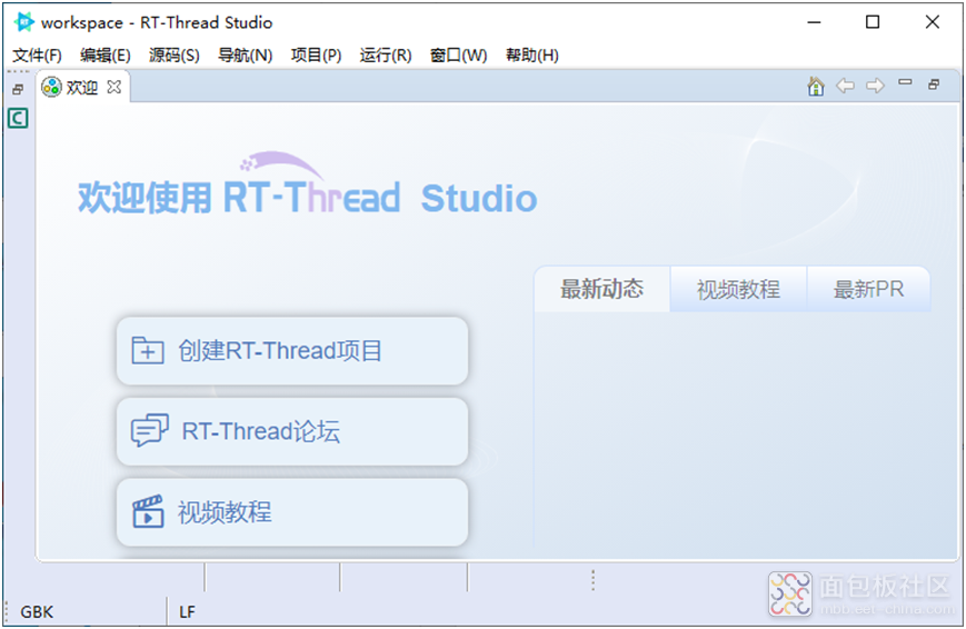
图4 初始界面
为了添加对RA6M4的支持,需打开SDK管理器,见图5所示。

图5 打开SDK管理器
随后是选取“CPK-RA6M4”的最新版进行安装,见图6所示。
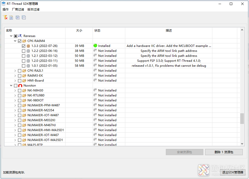
图6 添加RA6M4
在完成添加后,可创建一个新项目来进行程序下载测试。其操作为:在“文件”菜单下,选取“新建”中的“RT-Thread项目”,见图7所示。

图7 新建项目
随后,点击左侧项目资源栏中scr目录下的文件hal_entry.c,则界面如图8所示。
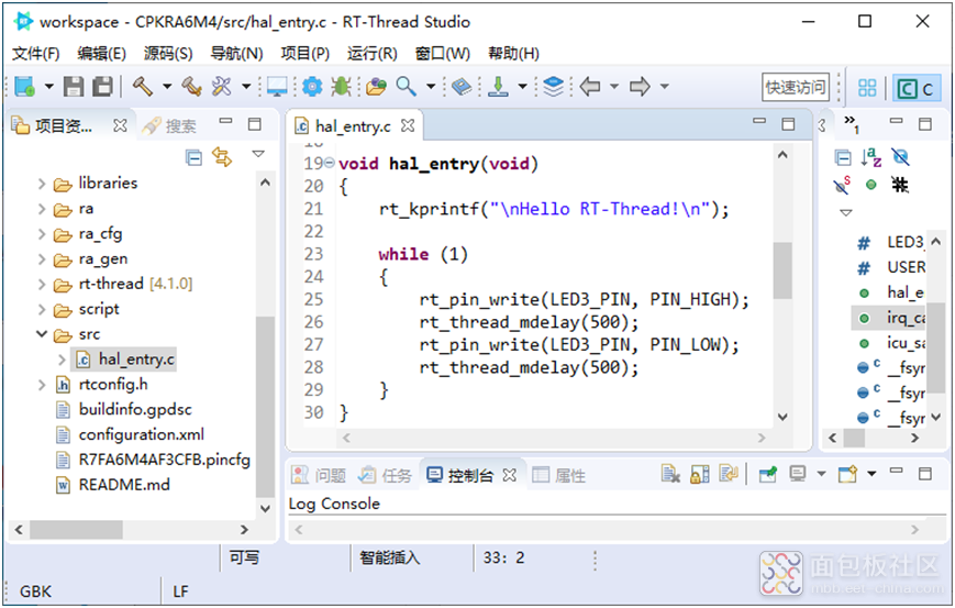
图8 打开例程
通过工具栏的编译图标可对程序进行编译,其结果如图9所示。
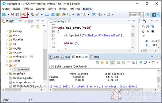
图9 完成编译
用USB线连接开发板的DEBUG接口和电脑,然后点击下载图标,则可完成程序的下载,见图10所示。
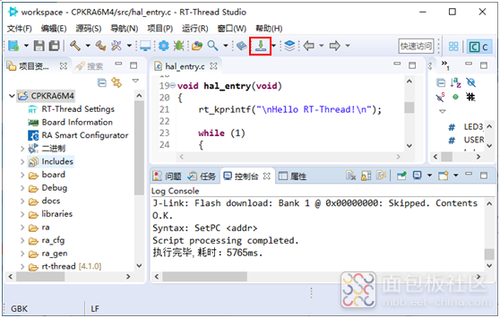
图10 完成下载
例程的主要程序为:
#define LED3_PIN BSP_IO_PORT_01_PIN_06#define USER_INPUT "P105" voidhal_entry(void) { rt_kprintf("\nHello RT-Thread!\n"); while (1) { rt_pin_write(LED3_PIN, PIN_HIGH); rt_thread_mdelay(500); rt_pin_write(LED3_PIN, PIN_LOW); rt_thread_mdelay(500); } }
复制代码由此可知,程序的作用是通过P106引脚来控制LED3,LED3的电路如图11所示。当其输出高电平时,LED3被点亮;而在其输出低电平时,则熄灭LED3;这便是程序控制LED3闪烁的原因。
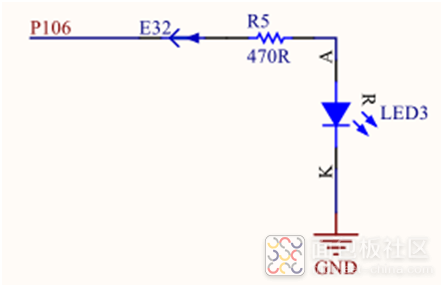
图11 LED电路
掌握了GPIO口的输出功能,就可以用来尝试OLED屏的显示驱动了。这里所用的是一款双色OLED屏,它采用的I2C接口。为输出高低电平,对所用引脚的定义为:#defineSCL_high rt_pin_write(BSP_IO_PORT_01_PIN_04, PIN_HIGH)#defineSCL_low rt_pin_write(BSP_IO_PORT_01_PIN_04, PIN_LOW)#defineSDA_high rt_pin_write(BSP_IO_PORT_01_PIN_07, PIN_HIGH)#defineSDA_low rt_pin_write(BSP_IO_PORT_01_PIN_07, PIN_LOW) 该OLED屏的初始化函数为:
void OLED_Init(void)复制代码{ OLED_WR_Byte(0xAE,OLED_CMD); OLED_WR_Byte(0x02,OLED_CMD); OLED_WR_Byte(0x10,OLED_CMD); OLED_WR_Byte(0x40,OLED_CMD); OLED_WR_Byte(0x81,OLED_CMD); OLED_WR_Byte(0xff,OLED_CMD); OLED_WR_Byte(0xA1,OLED_CMD); OLED_WR_Byte(0xC8,OLED_CMD); OLED_WR_Byte(0xA6,OLED_CMD); OLED_WR_Byte(0xA8,OLED_CMD); OLED_WR_Byte(0x3f,OLED_CMD); OLED_WR_Byte(0xD3,OLED_CMD); OLED_WR_Byte(0x00,OLED_CMD); OLED_WR_Byte(0xd5,OLED_CMD); OLED_WR_Byte(0x80,OLED_CMD); OLED_WR_Byte(0xD9,OLED_CMD); OLED_WR_Byte(0xF1,OLED_CMD); OLED_WR_Byte(0xDA,OLED_CMD); OLED_WR_Byte(0x12,OLED_CMD); OLED_WR_Byte(0xDB,OLED_CMD); OLED_WR_Byte(0x40,OLED_CMD); OLED_WR_Byte(0x20,OLED_CMD); OLED_WR_Byte(0x02,OLED_CMD); OLED_WR_Byte(0x8D,OLED_CMD); OLED_WR_Byte(0x14,OLED_CMD); OLED_WR_Byte(0xA4,OLED_CMD); OLED_WR_Byte(0xA6,OLED_CMD); OLED_WR_Byte(0xAF,OLED_CMD); OLED_WR_Byte(0xAF,OLED_CMD); OLED_Clear(); OLED_Set_Pos(0,0); }
通过GPIO口模拟I2C发送字节数据的函数为:
void Write_IIC_Byte(unsignedcharIIC_Byte){ unsignedchari; unsignedcharm,da; da=IIC_Byte; SCL_low; for(i=0;i<8;i++) { m=da; m=m&0x80; if(m==0x80) { SDA_high; } else SDA_low; da=da<<1; SCL_high; SCL_low; } }
复制代码在添加字符及字符串显示函数的情况下,实现图12所示效果的程序为:
void hal_entry(void){ OLED_Init(); OLED_Clear(); OLED_ShowString(20,0,"CPK-RA6M4",16); OLED_ShowCHinese(20,2,3); OLED_ShowCHinese(36,2,4); OLED_ShowCHinese(52,2,5); OLED_ShowString(20,4,"jinglixixi",16); while (1) { rt_pin_write(LED3_PIN, PIN_HIGH); rt_thread_mdelay(500); rt_pin_write(LED3_PIN, PIN_LOW); rt_thread_mdelay(500); } }
复制代码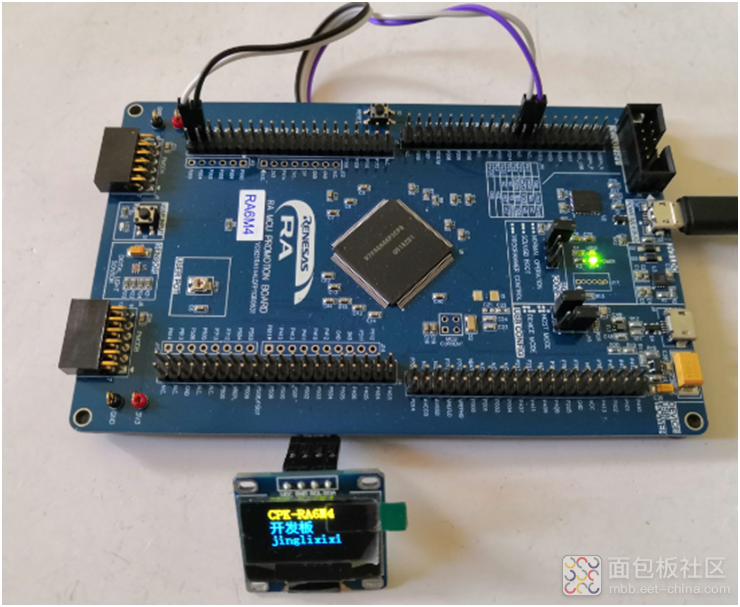
图12 OLED屏显示效果
此外,在开发板上配有Arduino接口,见图13所示。
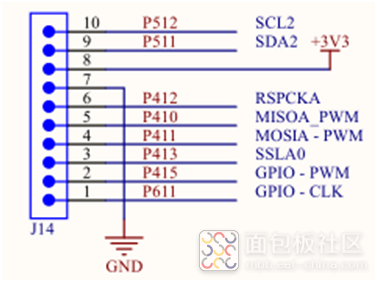
图13 Arduino接口
若修改所用引脚的定义,则可免去连接直接实现插接使用,见图14所示。
更新后的引脚定义为:
#defineSCL_highrt_pin_write(BSP_IO_PORT_04_PIN_12, PIN_HIGH)
#defineSCL_lowrt_pin_write(BSP_IO_PORT_04_PIN_12, PIN_LOW)
#defineSDA_highrt_pin_write(BSP_IO_PORT_04_PIN_10, PIN_HIGH)
#defineSDA_lowrt_pin_write(BSP_IO_PORT_04_PIN_10,PIN_LOW)
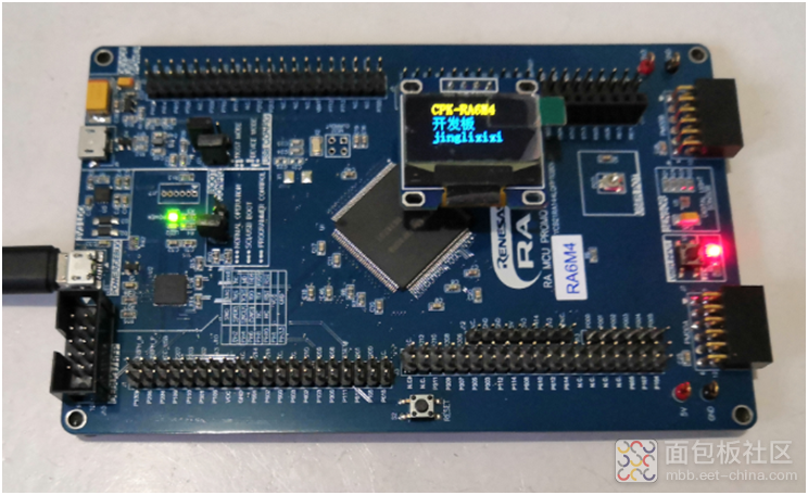
图14 OLED屏显示效果
另外,在开发板上还配有一个小按键,其电路如图15所示,在添加程序的情况下,可用S1来控制LED3。
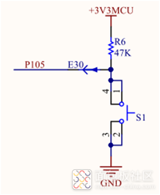
图15 KEY电路
使用S1来控制LED3的程序为:
#define S1_PIN BSP_IO_PORT_01_PIN_05rt_pin_mode(S1_PIN, PIN_MODE_INPUT_PULLUP ); while (1) { if (rt_pin_read(S1_PIN)==PIN_LOW) rt_pin_write(LED3_PIN, PIN_HIGH); else rt_pin_write(LED3_PIN, PIN_LOW); }
复制代码程序编译与下载后,其控制效果如图16所示。
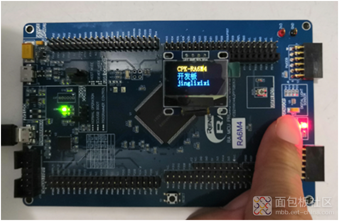
图16 按键控制
这样就基本掌握了GPIO口的使用方法,后面就可以展开相应的测评工作了。


 /4
/4 
