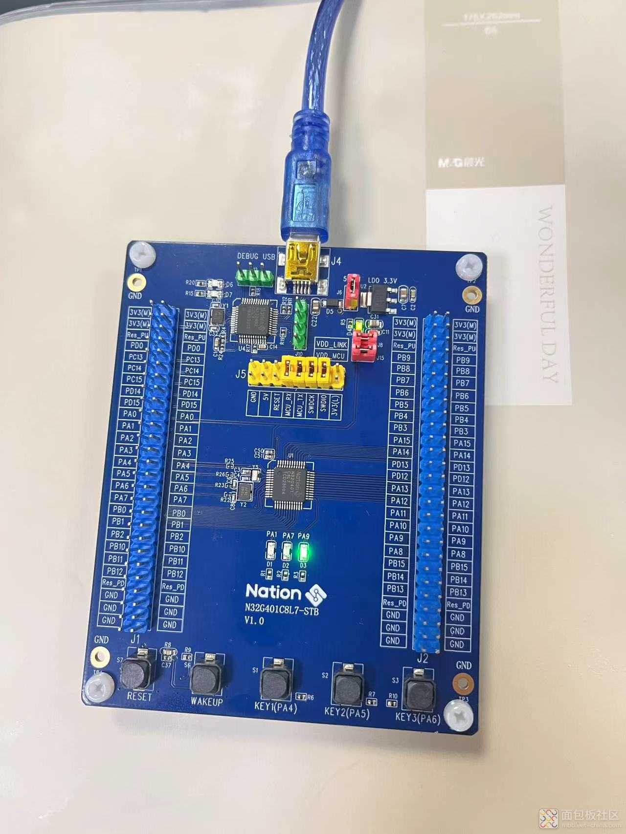
很庆幸能收到国民技术的开发板,感谢!!!

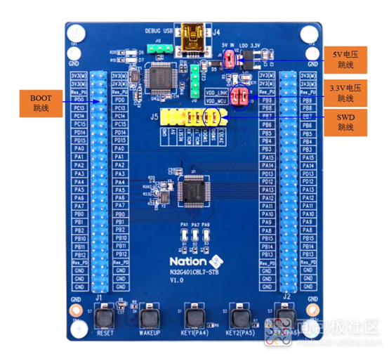
开发板图展示:

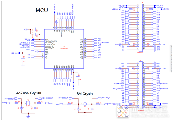
开发板原理图:

官方给的N32G401集成1个灵活的通用DMA控制器,支持8个DMA通道,可以管理存储器到存储器、外设到存储器和存储器到
外设的数据传输。
N32G401系列产品中,集成了最多4个串行收发接口,包括2个通用同步/异步收发器(USART1和USART2)和 2个通用异步收发器(UART3和UART4)。
官方给的串口USART1和USART2接口具有硬件的CTS和RTS信号管理、兼容ISO7816的智能卡模式和类SPI通信模式,所有接口都可以使用DMA操作。
所以,我想验证下通过DMA发送串口功能。1、首先自定义一行打印数据
USART_InitType USART_InitStructure;
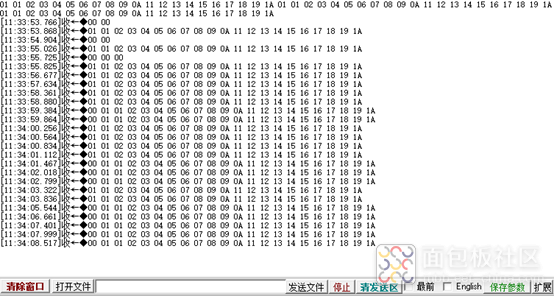
uint8_t TxBuffer1[20] = {0x01,0x02,0x03,0x04,0x05,0x06,0x07,0x08,0x09,0x0a,0x11,0x12,0x13,0x14,0x15,0x16,0x17,0x18,0x19,0x1a};
复制代码2、配置DMA、GPIO、USART相关的时钟
void RCC_Configuration(void)
{
/* DMA clock enable */
RCC_AHB_Peripheral_Clock_Enable(RCC_AHB_PERIPH_DMA);
/* Enable GPIO clock */
RCC_AHB_Peripheral_Clock_Enable(RCC_AHB_PERIPH_GPIOA);
RCC_APB2_Peripheral_Clock_Enable(RCC_APB2_PERIPH_AFIO);
/* Enable USARTy and USARTz Clock */
USARTy_APBxClkCmd(RCC_APB2_PERIPH_USART1);
}
复制代码3、配置 GPIO 引脚
void GPIO_Configuration(void)
{
GPIO_InitType GPIO_InitStructure;
/* Initialize GPIO_InitStructure */
GPIO_Structure_Initialize(&GPIO_InitStructure);
/* Configure USARTy Tx as alternate function push-pull */
GPIO_InitStructure.Pin = GPIO_PIN_9;
GPIO_InitStructure.GPIO_Mode = GPIO_MODE_AF_PP;
GPIO_InitStructure.GPIO_Alternate = GPIO_AF5_USART1;
GPIO_Peripheral_Initialize(GPIOA, &GPIO_InitStructure);
/* Configure USARTx Rx as alternate function push-pull */
GPIO_InitStructure.Pin = GPIO_PIN_10;
GPIO_InitStructure.GPIO_Alternate = GPIO_AF5_USART1;
GPIO_Peripheral_Initialize(GPIOA);
}
复制代码void DMA_Configuration(void)
{
DMA_InitType DMA_InitStructure;
/* DMA_CH1 (triggered by USARTy Tx event) Config */
DMA_Reset(DMA_CH1);
DMA_InitStructure.PeriphAddr = (USART1_BASE + 0x04);
DMA_InitStructure.MemAddr = (uint32_t)TxBuffer1;
DMA_InitStructure.Direction = DMA_DIR_PERIPH_DST;
DMA_InitStructure.BufSize = TxBufferSize1;
DMA_InitStructure.PeriphInc = DMA_PERIPH_INC_MODE_DISABLE;
DMA_InitStructure.MemoryInc = DMA_MEM_INC_MODE_ENABLE;
DMA_InitStructure.PeriphDataSize = DMA_PERIPH_DATA_WIDTH_BYTE;
DMA_InitStructure.MemDataSize = DMA_MEM_DATA_WIDTH_BYTE;
DMA_InitStructure.CircularMode = DMA_CIRCULAR_MODE_DISABLE;
DMA_InitStructure.Priority = DMA_CH_PRIORITY_HIGHEST;
DMA_InitStructure.Mem2Mem = DMA_MEM2MEM_DISABLE;
DMA_Initializes(DMA_CH1);
DMA_Channel_Request_Remap(DMA_CH1,DMA_REMAP_USART1_TX);
}
复制代码void usart_config(){
/* USART1 and USARTz configuration */
USART_InitStructure.BaudRate = 115200;
USART_InitStructure.WordLength = USART_WL_8B;
USART_InitStructure.StopBits = USART_STPB_1;
USART_InitStructure.Parity = USART_PE_NO;
USART_InitStructure.HardwareFlowControl = USART_HFCTRL_NONE;
USART_InitStructure.Mode = USART_MODE_RX | USART_MODE_TX;
/* Configure USART1 and USARTz */
USART_Initializes(USART1, &USART_InitStructure);
/* Enable USART1 DMA Rx and TX request */
USART_DMA_Transfer_Enable(USART1, USART_DMAREQ_RX | USART_DMAREQ_TX);
/* Enable USART1 TX DMA Channel */
DMA_Channel_Enable(DMA_CH1);
/* Enable the USART1 and USARTz */
USART_Enable(USART1);
}
复制代码6、测试
int main(void)
{
/* System Clocks Configuration */
RCC_Configuration();
/* NVIC configuration */
NVIC_Configuration();
/* Configure the GPIO ports */
GPIO_Configuration();
/* Configure the DMA */
DMA_Configuration();
usart_config();
while(1){
DMA_Channel_Disable(DMA_CH1);
DMA_Current_Data_Transfer_Number_Set(DMA_CH1, 20);
DMA_Channel_Enable(DMA_CH1);
while (USART_Flag_Status_Get(USART1, USART_FLAG_RXDNE) == RESET)
{
}
__NOP();
__NOP();
__NOP();
}
}
复制代码
说明:
使用DMA来处理USART数据传输主要是为了提高传输效率、减轻CPU的负担、避免频繁的中断处理,并且在需要进行大数据量、实时性要求高的场景中表现尤为优越。
所以经常会DMA与USART配合使用,这样能让系统在保持高性能的同时,减少延迟和数据丢失的风险。


 /5
/5 


