面包板 DIY / 拆解千元奖励活动: https://mbb.eet-china.com/t/diy/59670你想要学习如何制作你自己的机器人吗?制作机器人是自学电子学和计算机编程的一种非常好的方式。wikihow这个教程详细介绍了制作一个机器人的步骤:组装机器人;给机器人接线;连接电源 ;安装Arduino软件;给机器人编程。
第一步:组装机器人
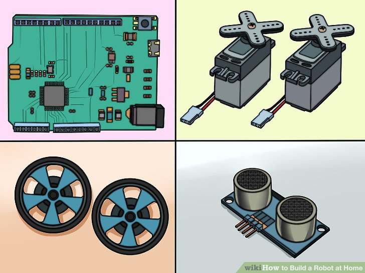
1.收集元件。为了制作一个基本的机器人,你将需要一些简单元件。你能从附近的业余爱好者商店或者在线零售店买到大部分元件(如果不是全部的话)。一些基本的工具包也可能包括所有的元件。这款机器人不需要很多的焊料。
- Arduino UNO(或者其他的微控制器)
- 2个连续旋转舵机
- 2个适合上述舵机的轮子
- 1个连铸机辊
- 1个小型无焊料的试验电路板(要找一个每边有两个正负线的电路板)
- 1个远程传感器(有四脚连接器电缆)
- 1个包含1个1万欧姆的电阻的按钮开关
- 1套线对板连接器
- 1个6 x AA的电池支架,包含一个9V DC插座
- 1包跨接线或者22 gauge的布线用电线
- 强力双面胶带或者热粘接剂
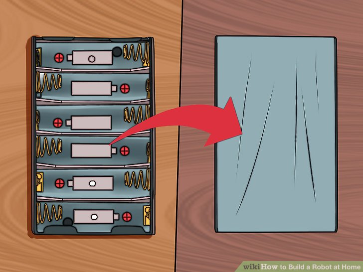
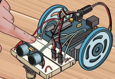
2.翻转电池支架,背面朝上。你将会用这个电池支架作为机器人身体的基础
3.将两个舵机与电池支架末端对齐。这应该是电池支架的电线伸出来的末端。舵机应该触到底部,并且每个舵机的旋转部分应该在电池支架的两边。舵机被合理的对齐是很重要的,这是为了让轮子放的直一些。端机的电线应该从电池支架的背部出来。
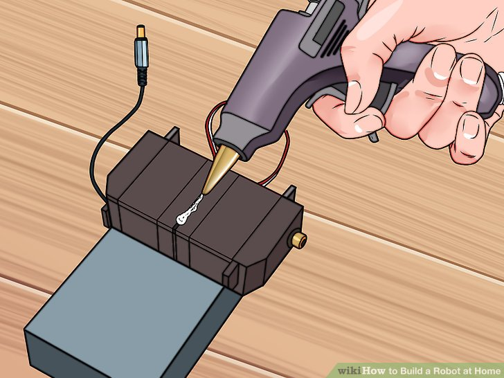
4.用胶带或胶水黏贴舵机。确定它们被牢牢地粘在一起。舵机的背部应该和电池支架的背部紧紧地贴在一起。
舵机现在应该占了电池支架背部的一半
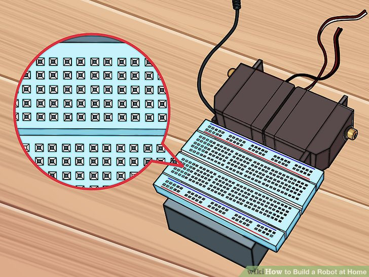
5.将电路板平行贴在电池支架背部空下的区域上。它应该距离电池支架前端有一点点距离,横向在电池支架两边应该露出一小部分。在下一步之前,确定它粘附的很牢。“A”排应该很接近舵机。
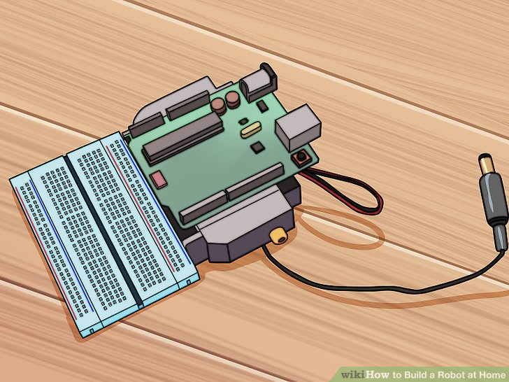
6.将Arduino微控制器粘在舵机的顶部。如果两个舵机放的很合适的话,应该它们之间的接触部分应该有一段平的区域。将Arduino微控制器放在这部分区域上,以使Arduino的USB和电源线朝后(远离电路板)。Arduino的前端应该刚刚与线路板有重叠。
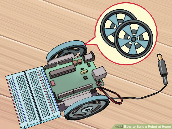
7.将轮子装在舵机上。将轮子紧紧的装到舵机的旋转部分中。这可能需要很大的力量,因为轮子被设计目的就是为了紧紧嵌入舵机来提供最大的牵引力。
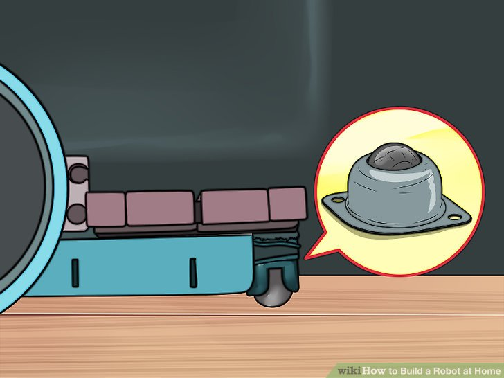
8.将连铸辊接在接线板底部。如果你把机身反过来,你应该看到电路板露在外边一点。将连铸辊装到露在外面的部分,必要的话使用冒口。连铸辊的作用是前轮,方便机器人转向。
如果你买了一个工具包,里面可能附带了一些对应连铸辊的冒口,以保证连铸辊接触地面。
第二步:给机器人接线
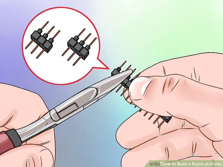
1.改造两个三脚连接器。你将用这些将舵机连到电路板上。移动针部,让两边距离相等。
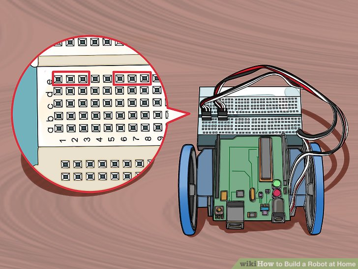
2.插入两个连接器到电路板E排的1-3插口和6-8插口。确定它们被牢牢的插入。
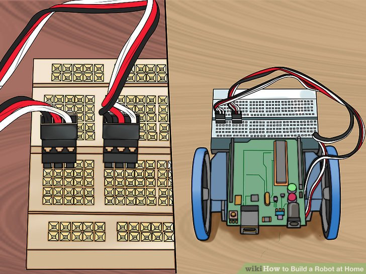
3.将舵机电缆连到连接器上,黑色电缆在左边。(接到1口和6口上)。这会将舵机与电路板连接在一起。确定左边的舵机连接到左边的连接器上,右边的舵机连接到右边的连接器上。
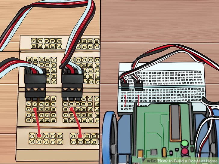
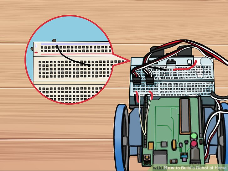
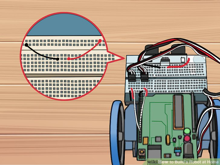
4.红色跨接线分别从C2针和C7针连到红色导轨(正级)针上。确定你用的是电路板后部的红色导轨针(red rail)(靠近机身的其他部分区域的红色导轨针)。
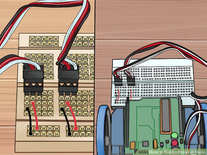
5.将黑色跨接线分别从B1针和B6针接到蓝色导轨针(地线)上。确定你用的是电路板后部的蓝色导轨针(blue rail pins)。不要插到红色导轨针上。
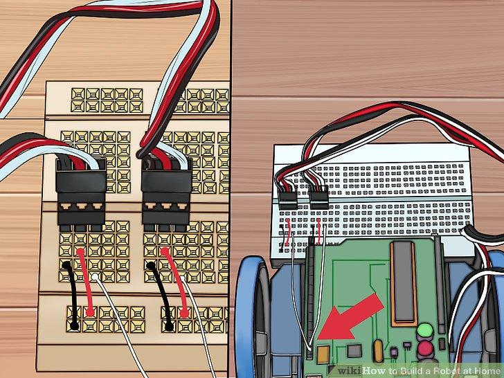
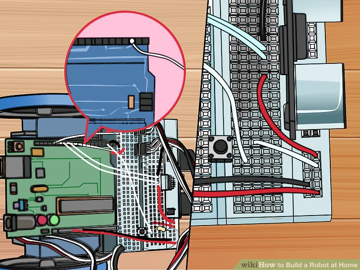
6.白色跨接线从Arduino 的针12和针13连接到A3和A8上。这让Arduino控制这些舵机和轮子。
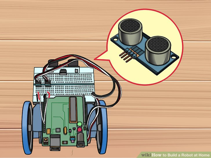
7.将传感器装到电路板前面。它不能插到电路板的外部电源区域中,应该插到第一排J行中。确定你精确地插到了中间区域,两边有数量相等的针数剩余。
8.黑色跨接线连接针I14和传感器左侧第一个可用的蓝色针。这会让传感器接地。
9.黑色跨接线连接针I 17和传感器右侧第一个可用的红色针。这给传感器提供电力。
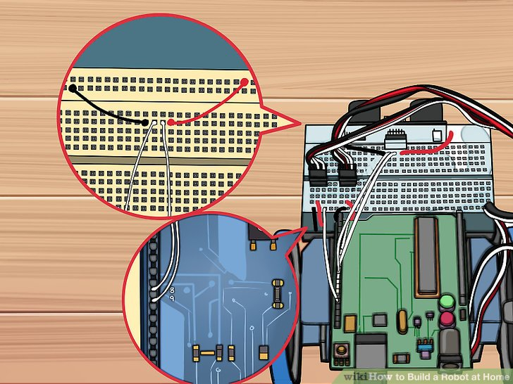
10.白色跨接线连接针I 15和Arduino上的针9,类似地,再连接针I16和针8。这将传感器的信息提供给微控制器。
第三步:连接电源
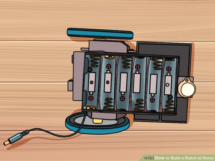
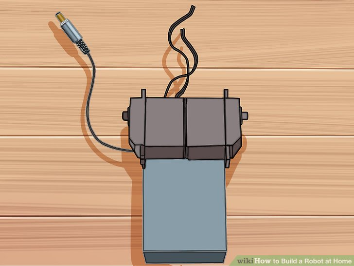
1.翻转机身,看到支架中的电池。让其电池支架的电缆线从左下角伸出。
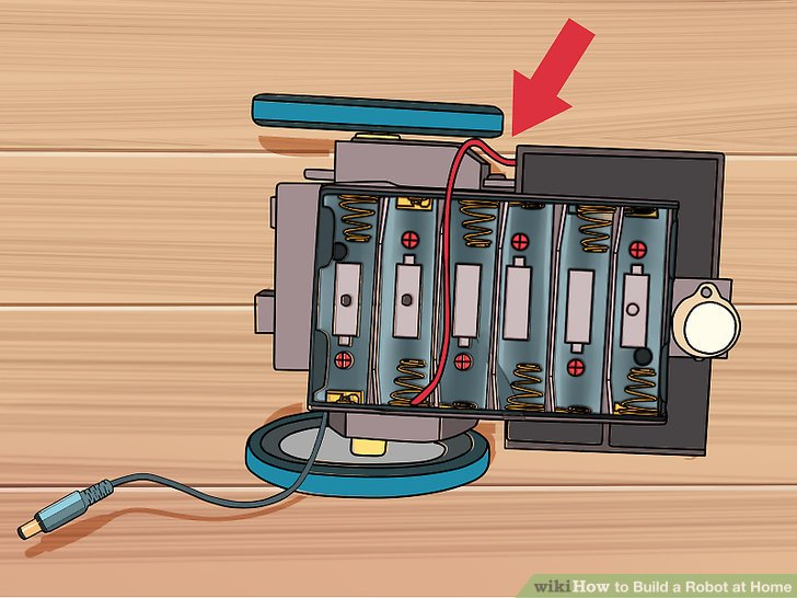
2.用红色的电缆线连接左下角的弹簧。一定要确定电池支架放置正确。
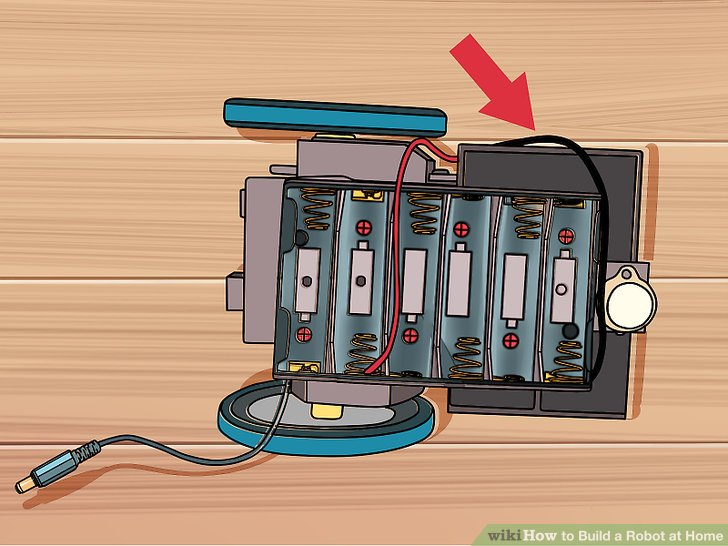
3.用黑色电缆线连接右下角最后一个弹簧。这两个电线给Arduino提供正确的电压。
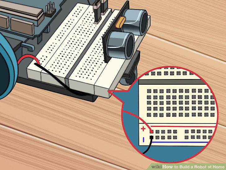
4.将上述红色和黑色的电线连到电路板最右边红色和蓝色的针上。黑色电线应该插入到蓝色导轨针的针30处。红色电缆线应该插到红色电缆线的针30处。
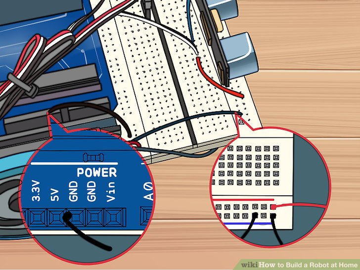
5.黑色电线连接Arduino上的GND针和电路板后部的蓝色导轨针。蓝色导轨针处连接位置是针28.
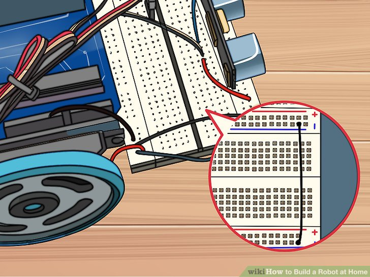
6.一个黑色电线连接电路板后部的蓝色导轨针和前部的蓝色导轨针(位置均在针29处)。不要连接红色导轨,因为那样很可能损坏Arduino。
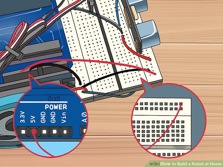
7.连接电路板前部的红色导轨针(针30)到Arduino上的5V针。这将会给Arduino提供电力。
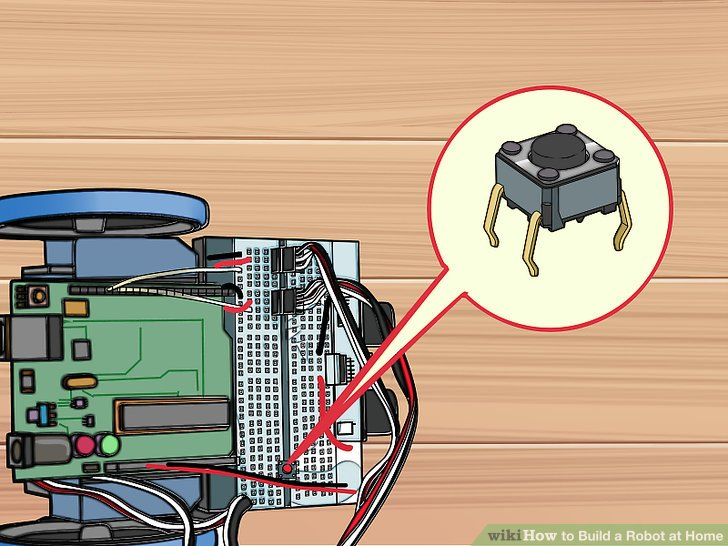
8.在两排的间隔处pin24-26处插入按钮开关。这个开关让你不需要通过拔电源就能关闭机器人。
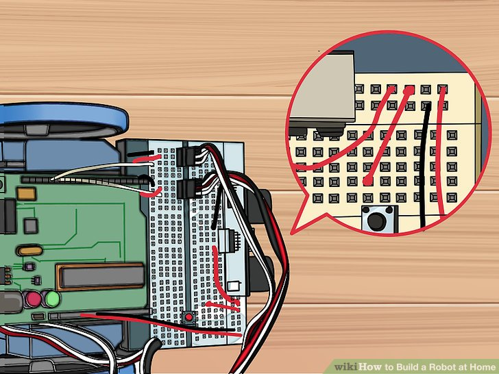
9.用一根红色线连接H24和传感器右侧下一个可用的针。这会给按钮提供电力。
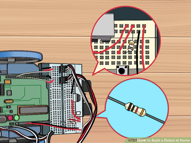
10.用电阻连接H26和蓝色导轨针。直接将电阻与针连接,并连到几步之前用到的黑色线旁边。
11.用一根白色线连接G26和Arduino的针2处。这让Arduino在按钮那里注册。
第四步:安装Arduino软件
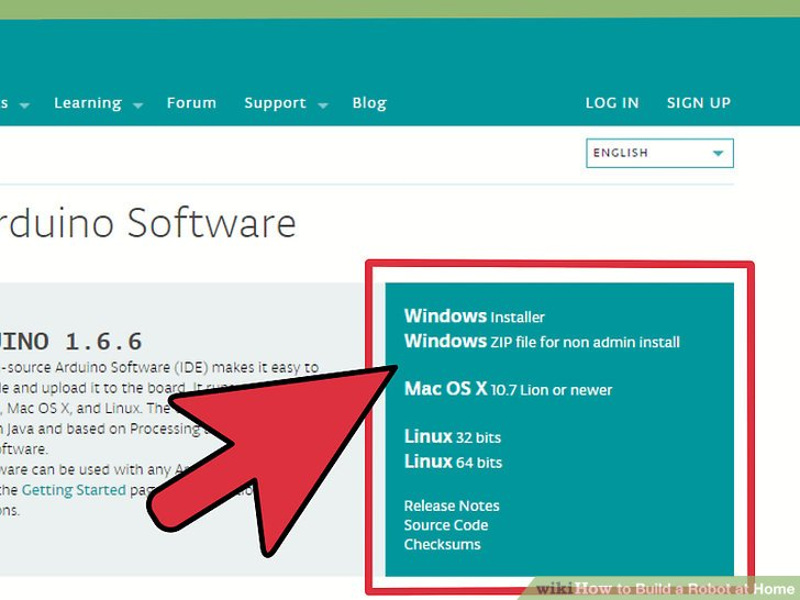
1.下载并提取Arduino IDE。这是Arduino的开发环境,这样,你可以将指令编程并上传到你的Arduino微型控制器中。你可以从arduino.cc/en/main/software网站中免费下载它。解压下载下来的文件,找到该文件夹,不需要安装程序,只需要双击arduino.exe来运行它。
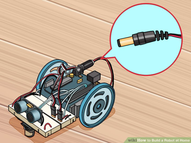
2.将电池架连到Arduino上。给Arduino的连接器接上电池组来为其提供电力。
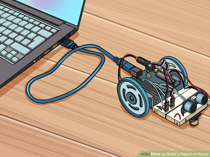
3.用USB将Arduino接入电脑。Windows很有可能不识别这个设备。
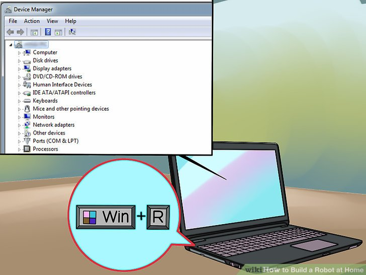
4.按下win+R,并输入“devmgmt.msc”。这会调出设备管理器。
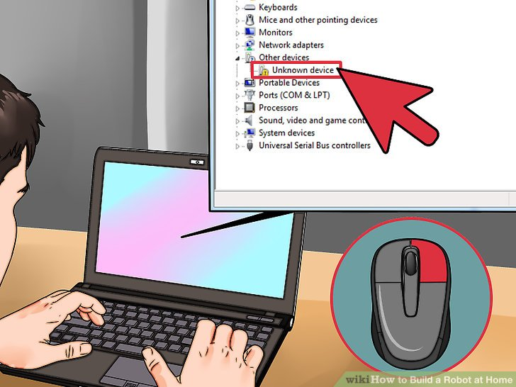
5.右击在“其他设备”选项中的“未知设备”,并选择“更新驱动软件”。如果你没有看到这个选项,点击“属性”,选择“驱动”标签,接着点击“更新驱动”。
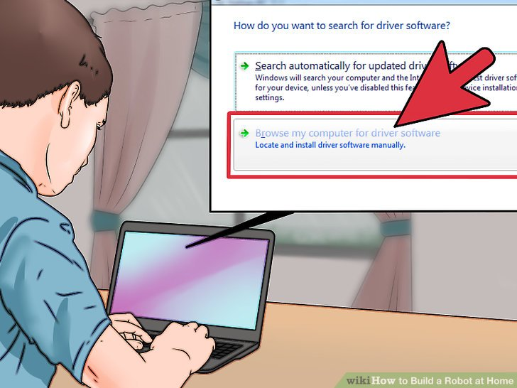
6.选择“浏览我的电脑来寻找驱动软件。”选择Arduino IDE中自带的驱动软件。
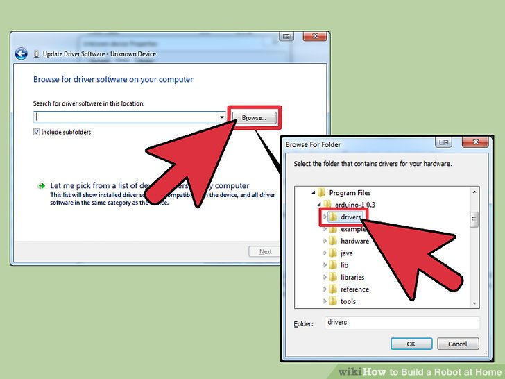
7.点击“浏览”,接着找到你之前下载并解压好的文件夹。你会在文件夹里找到一个名为“drivers”的文件夹。
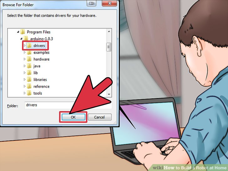
8.选择“drivers”文件夹,并点击“确定”。如果你被警告“这是未知软件”,确认你想要继续。
第五步:为机器人编程
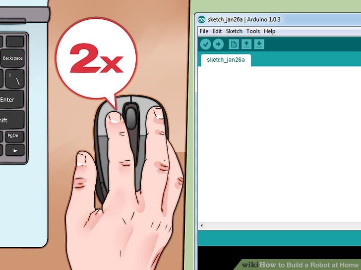
1.双击IDE文件夹中的“arduino.exe”启动Arduino IDE。你会看到一个空白的工程。
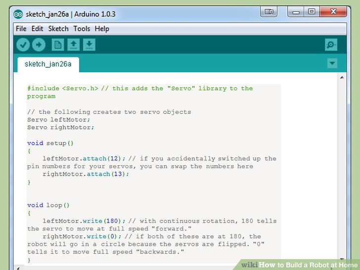
- 粘贴以下代码来让你的机器人可以走直线。以下的代码将会让你的Arduino不停地前进。
#include <Servo.h> // this adds the "Servo" library to the program // the following creates two servo objects Servo leftMotor; Servo rightMotor; void setup() { leftMotor.attach(12); // if you accidentally switched up the pin numbers for your servos, you can swap the numbers here rightMotor.attach(13); } void loop() { leftMotor.write(180); // with continuous rotation, 180 tells the servo to move at full speed "forward." rightMotor.write(0); // if both of these are at 180, the robot will go in a circle because the servos are flipped. "0" tells it to move full speed "backwards." }
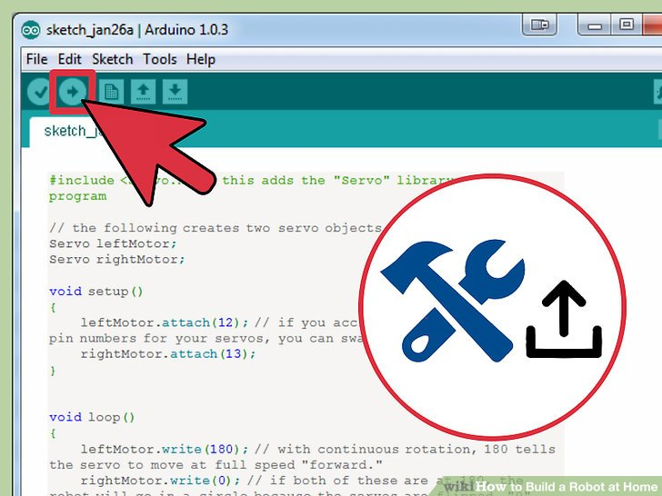
3.构建并上传代码。点击左上角的“向右的箭头”来将代码构建并上传到USB连接着的Arduino。
你可能想要把机器人拿起来,因为一旦代码上传好,它会继续向前移动。
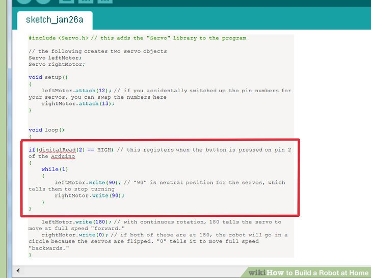
4.增加关闭功能。增加代码以下到源代码的“void loop()”部分中来激活关闭功能。具体位置在“void loop()”中“write()”函数上面。
if(digitalRead(2) == HIGH) // this registers when the button is pressed on pin 2 of the Arduino { while(1) { leftMotor.write(90); // "90" is neutral position for the servos, which tells them to stop turning rightMotor.write(90); } }
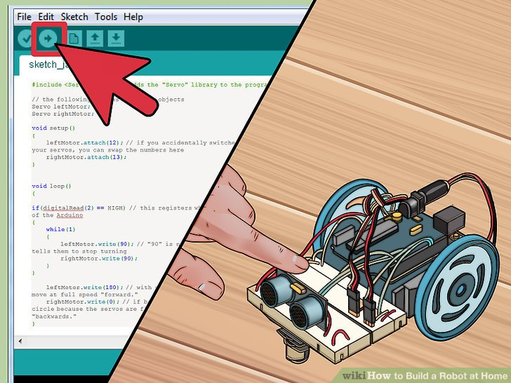
5.上传并测试你的代码。有了增加后的关闭功能,你可以上传并测试机器人了。它应该在你按下按钮之前不停的前进,当你按完后,它会停止。全部代码如下
#include <Servo.h> // the following creates two servo objects Servo leftMotor; Servo rightMotor; void setup() { leftMotor.attach(12); rightMotor.attach(13); } void loop() { if(digitalRead(2) == HIGH) { while(1) { leftMotor.write(90); rightMotor.write(90); } } leftMotor.write(180); rightMotor.write(0); } 示例:
这里提供一份示例代码,它用了机器人身上的传感器,来让它在遇到障碍时向左转。代码中的注释解释了代码每个部分是用来做什么的。
#include <Servo.h> Servo leftMotor; Servo rightMotor; const int serialPeriod = 250; // this limits output to the console to once every 1/4 second unsigned long timeSerialDelay = 0; const int loopPeriod = 20; // this sets how often the sensor takes a reading to 20ms, which is a frequency of 50Hz unsigned long timeLoopDelay = 0; // this assigns the TRIG and ECHO functions to the pins on the Arduino. Make adjustments to the numbers here if you connected differently const int ultrasonic2TrigPin = 8; const int ultrasonic2EchoPin = 9; int ultrasonic2Distance; int ultrasonic2Duration; // this defines the two possible states for the robot: driving forward or turning left #define DRIVE_FORWARD 0 #define TURN_LEFT 1 int state = DRIVE_FORWARD; // 0 = drive forward (DEFAULT), 1 = turn left void setup() { Serial.begin(9600); // these sensor pin configurations pinMode(ultrasonic2TrigPin, OUTPUT); pinMode(ultrasonic2EchoPin, INPUT); // this assigns the motors to the Arduino pins leftMotor.attach(12); rightMotor.attach(13); } void loop() { if(digitalRead(2) == HIGH) // this detects the kill switch { while(1) { leftMotor.write(90); rightMotor.write(90); } } debugOutput(); // this prints debugging messages to the serial console if(millis() - timeLoopDelay >= loopPeriod) { readUltrasonicSensors(); // this instructs the sensor to read and store the measured distances stateMachine(); timeLoopDelay = millis(); } } void stateMachine() { if(state == DRIVE_FORWARD) // if no obstacles detected { if(ultrasonic2Distance > 6 || ultrasonic2Distance < 0) // if there's nothing in front of the robot. ultrasonicDistance will be negative for some ultrasonics if there is no obstacle { // drive forward rightMotor.write(180); leftMotor.write(0); } else // if there's an object in front of us { state = TURN_LEFT; } } else if(state == TURN_LEFT) // if an obstacle is detected, turn left { unsigned long timeToTurnLeft = 500; // it takes around .5 seconds to turn 90 degrees. You may need to adjust this if your wheels are a different size than the example unsigned long turnStartTime = millis(); // save the time that we started turning while((millis()-turnStartTime) < timeToTurnLeft) // stay in this loop until timeToTurnLeft has elapsed { // turn left, remember that when both are set to "180" it will turn. rightMotor.write(180); leftMotor.write(180); } state = DRIVE_FORWARD; } } void readUltrasonicSensors() { // this is for ultrasonic 2. You may need to change these commands if you use a different sensor. digitalWrite(ultrasonic2TrigPin, HIGH); delayMicroseconds(10); // keeps the trig pin high for at least 10 microseconds digitalWrite(ultrasonic2TrigPin, LOW); ultrasonic2Duration = pulseIn(ultrasonic2EchoPin, HIGH); ultrasonic2Distance = (ultrasonic2Duration/2)/29; } // the following is for debugging errors in the console. void debugOutput() { if((millis() - timeSerialDelay) > serialPeriod) { Serial.print("ultrasonic2Distance: "); Serial.print(ultrasonic2Distance); Serial.print("cm"); Serial.println(); timeSerialDelay = millis(); } } 此文由
来源:wikiHow
译者:新智元 / 张巨岩


 /5
/5