1、功耗,超低功耗之王蓝牙BLE SOC
RSL10在深度睡眠模式下、电压1.25 V时消耗的电流为50 nA,在0 dBm时的传输(Tx)和接收(Rx)峰值分别为8.9 mA和5.6 mA。
2、性能
RSL10的Rx灵敏度达到-94 dBm,采用384 kB闪存,双核处理器(ARM® Cortex®-M3处理器、32位Dual-Harvard数字信号处理DSP系统),适用于各种不同传感器的GPIO、LSAD、I2C、SPI、PCM等模拟和数字接口,用户可根据需要进行编程。
3、超微型
RSL10采用55 nm技术,其WLCSP封装版本仅5.5平方毫米。SOC内置天线,模块封装体积最小。
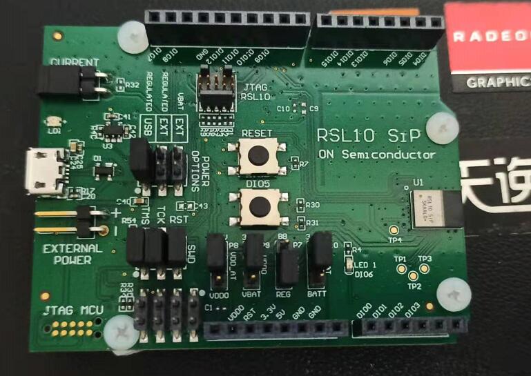
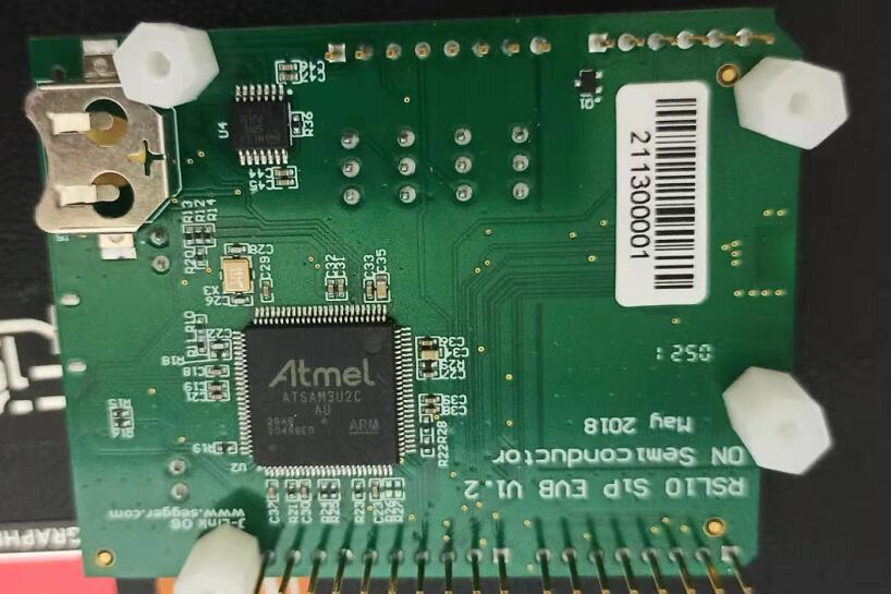
开发板搭载JLINK
支持keil, ON Semiconductor IDE
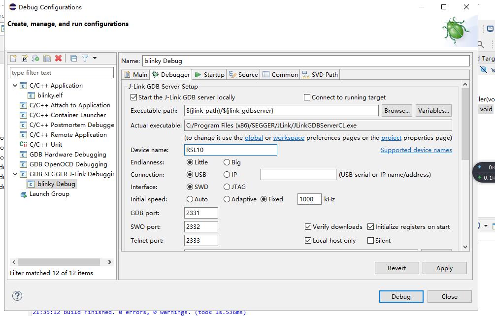
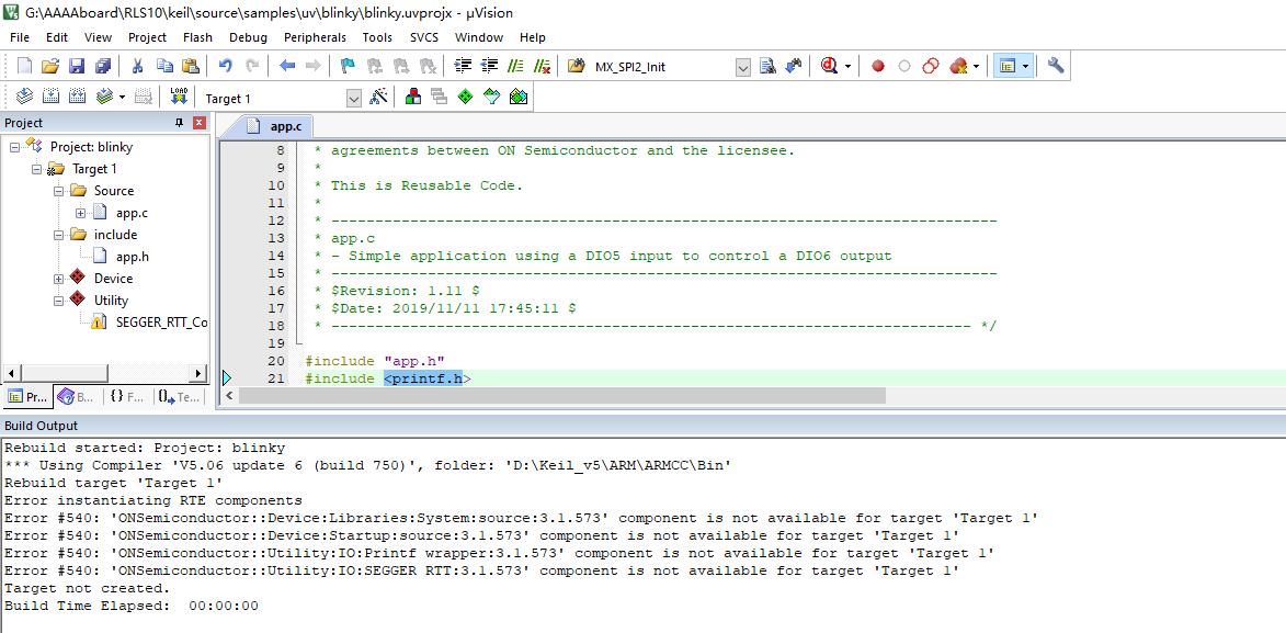
ON Semiconductor IDE下载还有些问题,需要继续研究。
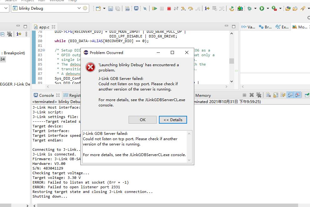
先放个APP 源码;
/* ---------------------------------------------------------------------------- * Copyright (c) 2017 Semiconductor Components Industries, LLC (d/b/a * ON Semiconductor), All Rights Reserved * * This code is the property of ON Semiconductor and may not be redistributed * in any form without prior written permission from ON Semiconductor. * The terms of use and warranty for this code are covered by contractual * agreements between ON Semiconductor and the licensee. * * This is Reusable Code. * * ---------------------------------------------------------------------------- * app.c * - Simple application using a DIO5 input to control a DIO6 output * ---------------------------------------------------------------------------- * $Revision: 1.11 $ * $Date: 2019/11/11 17:45:11 $ * ------------------------------------------------------------------------- */ #include "app.h" #include <printf.h> /* ---------------------------------------------------------------------------- * Function : void DIO0_IRQHandler(void) * ---------------------------------------------------------------------------- * Description : Toggle the toggle status global flag. * Inputs : None * Outputs : None * Assumptions : None * ------------------------------------------------------------------------- */ void DIO0_IRQHandler(void) { static uint8_t ignore_next_dio_int = 0; if (ignore_next_dio_int == 1) { ignore_next_dio_int = 0; } else if (DIO_DATA->ALIAS[BUTTON_DIO] == 0) { /* Button is pressed: Ignore next interrupt. * This is required to deal with the debounce circuit limitations. */ ignore_next_dio_int = 1; /* Invert toggle status */ if (led_toggle_status == 1) { led_toggle_status = 0; PRINTF("LED BLINK DISABLED\n"); } else { led_toggle_status = 1; PRINTF("LED BLINK ENABLED\n"); } } } /* ---------------------------------------------------------------------------- * Function : void Initialize(void) * ---------------------------------------------------------------------------- * Description : Initialize the system by disabling interrupts, configuring * the required DIOs and DIO interrupt, * updating SystemCoreClockUpdate and enabling interrupts. * Inputs : None * Outputs : None * Assumptions : None * ------------------------------------------------------------------------- */ void Initialize(void) { /* Mask all interrupts */ __set_PRIMASK(PRIMASK_DISABLE_INTERRUPTS); /* Disable all existing interrupts, clearing all pending source */ Sys_NVIC_DisableAllInt(); Sys_NVIC_ClearAllPendingInt(); /* Test DIO12 to pause the program to make it easy to re-flash */ DIO->CFG[RECOVERY_DIO] = DIO_MODE_INPUT | DIO_WEAK_PULL_UP | DIO_LPF_DISABLE | DIO_6X_DRIVE; while (DIO_DATA->ALIAS[RECOVERY_DIO] == 0); /* Setup DIO5 as a GPIO input with interrupts on transitions, DIO6 as a * GPIO output. Use the integrated debounce circuit to ensure that only a * single interrupt event occurs for each push of the pushbutton. * The debounce circuit always has to be used in combination with the * transition mode to deal with the debounce circuit limitations. * A debounce filter time of 50 ms is used. */ Sys_DIO_Config(LED_DIO, DIO_MODE_GPIO_OUT_0); Sys_DIO_Config(BUTTON_DIO, DIO_MODE_GPIO_IN_0 | DIO_WEAK_PULL_UP | DIO_LPF_DISABLE); Sys_DIO_IntConfig(0, DIO_EVENT_TRANSITION | DIO_SRC(BUTTON_DIO) | DIO_DEBOUNCE_ENABLE, DIO_DEBOUNCE_SLOWCLK_DIV1024, 149); NVIC_EnableIRQ(DIO0_IRQn); printf_init(); /* Unmask all interrupts */ __set_PRIMASK(PRIMASK_ENABLE_INTERRUPTS); } /* ---------------------------------------------------------------------------- * Function : int main(void) * ---------------------------------------------------------------------------- * Description : Initialize the system, then toggle DIO6 as controlled by * DIO5 (press to toggle input/output). * Inputs : None * Outputs : None * Assumptions : None * ------------------------------------------------------------------------- */ int main(void) { /*Initialize global variables */ led_toggle_status = 1; /* Initialize the system */ Initialize(); PRINTF("DEVICE INITIALIZED\n"); /* Spin loop */ while (1) { /* Refresh the watchdog timer */ Sys_Watchdog_Refresh(); /* Toggle GPIO 6 (if toggling is enabled) then wait 0.5 seconds */ if (led_toggle_status == 1) { Sys_GPIO_Toggle(LED_DIO); PRINTF("LED %s\n", (DIO->CFG[LED_DIO] & 0x1 ? "ON" : "OFF")); } else { Sys_GPIO_Set_Low(LED_DIO); } Sys_Delay_ProgramROM((uint32_t)(0.5 * SystemCoreClock)); } }
复制代码


 /5
/5 
