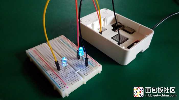
Raspberry Pi是一种了不起的小型机,我很想在某些项目中使用该设备。但是存在一个小问题,那就是我几乎没有任何Python经验。几年前,我曾经编写过Python代码,但是非常基础。我比较擅长C++,尤其是Arduino程序编写。那么我们有没有办法在Raspberry Pi上施展我们的Arduino编程技能呢?那样不是非常好吗?幸运的是,有办法!
本文将告诉您如何在Raspberry Pi上运行Arduino程序!为此,我们使用RasPiArduino框架。该架构能让我们把Arduino代码编译成可以在Raspberry Pi上运行的二进制文件。但是这样做之前,我们必须在Arduino IDE和Raspberry Pi上做一些准备。
硬件
- Raspberry Pi 3 Model B
- Arduino IDE
- RasPiArduino 架构 – https://github.com/me-no-dev/RasPiArduino
- MobaXterm – https://mobaxterm.mobatek.net/
Arduino IDE 设置
1. 打开Arduino安装文件夹。在Windows系统中,该文件夹的路径一般是“C:\Program Files\Arduino”(32位系统)或者“C:\Program Files(x86)\Arduino”(64位系统)。
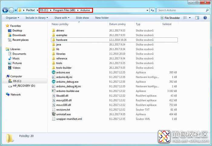
图1 Arduino安装文件夹
2. 打开文件夹“hardware”,并在该文件夹中创建一个名为“RaspberryPi”的新文件夹。
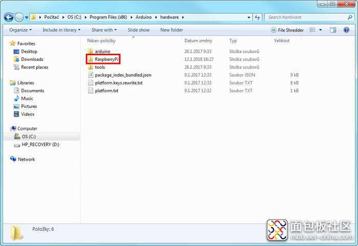
图2 新建的文件夹
3. 请打开以下链接https://github.com/me-no-dev/RasPiArduino,并将该库克隆到“RaspberryPi”内的新文件夹“piduino”中。如果您不想克隆该库,那么可以将库内容下载为zip文件,然后将其解压到“piduino”文件夹中。
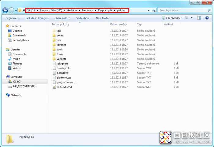
图3 “piduino”文件夹的内容
4. 接下来,您必须从以下链接https://gnutoolchains.com/raspberry/下载GNU Toolchain(工具链)。您必须下载支持当前所用Raspberry OS系统的Toolchain版本。由于您可能使用了最新的Raspbian Stretch,因此您需要下载GCC 6.3.0版本。下载完成之后,运行该文件。安装路径“C:\SysGCC\raspberry”保留不变,勾选接受许可协议,然后单击“Install”按钮。安装过程需要一点时间。
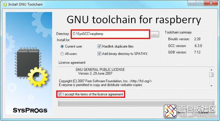
图4 GNU Toolchain安装程序
5. 请在Arduino安装目录中打开步骤3中创建的“piduino”文件夹。打开文件“platform.txt”,将第5行
runtime.tools.toolchain.path={runtime.platform.path}/tools/arm-linux-gnueabihf
改为
runtime.tools.toolchain.path=C:/SysGCC/Raspberry
这会将编译器指向我们在步骤4中安装的包含工具链的目录。

图5 platform.txt的内容
6. 重新启动Arduino IDE,打开一个新程序。现在,在“Tools”菜单的“Board”选项下面应该有一个名为“RaspberryPI B+/2”的新板。为了确保所有组件都正确安装,请选择Raspberry Pi板,复制下面的代码并编译程序。编译时间可能比Arduino开发板更长,而且中间会产生一些警告,但是只要最后显示“Done compiling”,就可以了。
void setup() {Console.println("This is the SETUP function"); } void loop() { Console.println("This is the LOOP function"); delay(1000); }
复制代码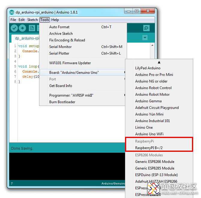
图6 Arduino IDE中的Raspberry Pi板
Raspberry Pi 设置
1. 请点击以下链接https://www.raspberrypi.org/downloads/,下载最新的Raspberry OS–Raspbian Stretch。将其安装到Raspberry(可以用NOOBS安装程序,也可以直接将其安装到SD卡)。
2. RasPiArduino 框架需要超级用户(root)权限才能运行,而且应该设置复杂密码进行保护。如果您已经在系统配置过程中设置了超级用户(root)密码,那么可以跳过此步骤。打开Raspberry终端,并输入以下命令
sudo su
您现在已经以超级用户(root)用户身份登录。请用以下命令设置密码
passwd
并在系统提示时再次输入密码进行确认。
3. 可选,但强烈建议执行此步骤。
本次配置的剩余部分都在Raspberry终端中完成。为了简便起见,我建议大家在电脑上用SSH通过本地网络控制Raspberry终端。否则的话,您还得在桌上放置另一个键盘和一个显示器,这会非常不方便。
在Raspberry上设置SSH非常简单,只需按照以下说明操作即可:https://www.raspberrypi.org/documentation/remote-access/ssh/。
SSH设置完成后,还得在电脑上下载某种SSH终端程序。我用的程序叫做MobaXterm,该终端程序对于个人使用是免费的,并且非常易于控制。它还支持SFTP(SSH文件传输协议),凭借此协议您可以通过拖放的方式将文件移动到Raspberry。通过SSH登录时,还必须强制输入超级用户(root)密码。为此,请使用以下命令:
sed -i “s/PermitRootLogin without-password/PermitRootLogin yes/” /etc/ssh/sshd_config
4. 现在,我们必须在启动时禁用串行控制台(Serial Console)。打开文件/boot/cmdline.txt,并将其内容更改为
dwc_otg.lpm_enable=0 console=tty1 root=/dev/mmcblk0p2 rootfstype=ext4 elevator=deadline fsck.repair=yes rootwait
5. 接下来是用下面的命令完全禁用串行TTY:
systemctl disable serial-getty@ttyAMA0
6. 现在,我们应禁止加载内核声音模块。为此,请使用以下命令:
sed -i “s/dtparam=audio=on/#dtparam=audio=on/” /boot/config.txt
7. 可选步骤。通过设置avahi服务,您可以直接从Arduino IDE上传Arduino程序,就好像在为普通的Arduino开发板编程一样。打开文件/etc/avahi/services/arduino.service(如果该文件不存在,请创建该文件),并将以下文本复制到其中:
<?xml version=”1.0″ standalone=’no’?><!–*-nxml-*–><!DOCTYPE service-group SYSTEM “avahi-service.dtd”> <service-group> <name replace-wildcards=”yes”>%h</name> <service> <type>_arduino._tcp</type> <port>22</port> <txt-record>board=bplus</txt-record> </service> </service-group>
复制代码service avahi-daemon restart
8. 安装telnet和git。在终端程序上,执行此操作的最简单方法就是使用包管理器。首先,请确保将包列表更新到最新版。
apt-get update
然后,安装telnet和git。
apt-get install telnet git
9. 将RasPiArduino框架程序库克隆到您的Raspberry中。
git clone https://github.com/me-no-dev/RasPiArduino.git piduino
克隆完成后,将所有重要文件做成可执行文件。
chmod +x piduino/tools/arpi_bins/*
然后,将其拷到用户目录下。
cp piduino/tools/arpi_bins/* /usr/local/bin
我们不需要其余的RasPiArduino框架文件库,因此您可以将其删除。
rm -rf piduino
10. 现在您必须为run-avrdude脚本创建符号链接。该脚本是我们在上一步中复制并将其变成可执行文件的RasPiArduino文件之一。
ln -s /usr/local/bin/run-avrdude /usr/bin/run-avrdude
11. 可选步骤。您可以同步网络时间,并让程序在系统启动时开始。首先,安装NTP(网络时间协议)实用工具。
apt-get install ntpdate
接下来,打开文件/etc/rc.local,将其内容更改为:
#!/bin/sh -e_IP=\$(hostname -I) || true if [ “\$_IP” ]; then printf “My IP address is %s\n” “\$_IP” fi # Sync Time ntpdate-debian -u > /dev/null # Start Sketch /usr/local/bin/run-sketch > /dev/null exit 0
复制代码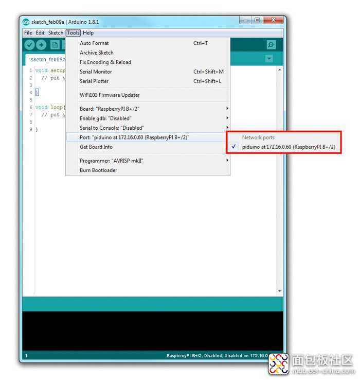
图7 Arduino IDE中的Raspberry Pi IP端口
如果按照上述步骤操作,您的Raspberry现在应该可以通过Arduino IDE进行编程了。对了,还有一个小细节需要讲一下。Arduino功能的核心是通过各种数字和模拟输入和输出与外界交互。Raspberry配有GPIO排针接头,其引脚映射和功能如下图所示。RasPiArduino Pin #(引脚编号)列中的数字与GPIO引脚编号相对应,程序中应使用该引脚编号。
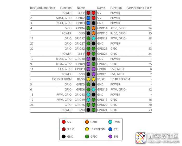
图8 RasPiArduino框架中的Raspberry Pi引脚映射
请注意,Raspberry Pi只有4个引脚具有PWM输出功能,没有可以读取模拟电压的引脚!此外,与大多数Arduino开发板不同,Raspberry运行在3.3V逻辑上——逻辑1对应3.3 V。Raspberry GPIO引脚无法承受5V电压!如果直接将5V电压施加到这些引脚上,那么很有可能会损坏Raspberry Pi!
基础示例:LED和控制台
理论描述到此为止,现在我们将其付诸实践!我们从最简单的Arduino基本功能开始:LED和串行输出。我使用的Arduino程序如下所示。我对Arduino的“淡入淡出”程序进行了简单修改。该程序通过PWM(脉冲宽度调制)调节LED的亮度,并将当前PWM值打印到控制台。
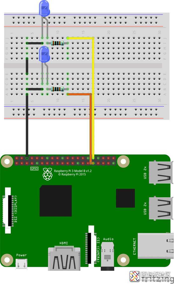
图9 本例的接线示意图
对Arduino开发板进行编程的最后一步:点击神奇的“Upload”按钮,然后系统会自动编译程序并将其上传到硬件中。在RasPiArduino框架下,将程序上传到Raspberry有两种方法。
1. 使用“Upload”按钮。将Raspberry连至您的本地网络,在“Tools”菜单中的“Ports”部分应该能看到其IP地址。选择该地址,就像选择Arduino COM端口一样,然后点击“Upload”。然后,系统会提示您输入超级用户(root)密码。输入后,系统会上传程序并自动执行。您可以在Arduino串行监视器中查看控制台输出结果。
2. 手动上传。在Arduino IDE中,进入菜单“Sketch”,然后点击“Export compiled binary”。系统会编译您的程序,并将二进制文件导出为.bin文件,文件的存放路径为程序文件夹。现在,我们得把此文件复制到Raspberry Pi。下一步是用以下命令将这个二进制文件变成可执行文件:
chmod +x exported_binary.bin
现在,您可以通过另一个命令来运行该二进制文件,必须以超级用户身份执行:
sudo ./exported_binary.bin
现在,所有控制台输出都将显示在控制台中。与其他任何终端程序一样,我们可以通过键盘快捷键Ctrl+C停止。我更喜欢手动上传,因为它不需要设置其他服务,并且通常更可靠(至少在我的配置中是这样的)。
请用以上两种方法其中的一种上传程序,然后观察两个LED。其中一个LED应该会不断闪烁,而另一个则会呈现淡入淡出效果!
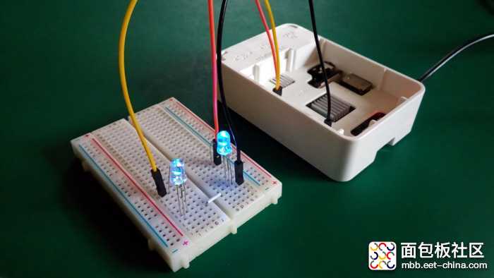
图10 Raspberry Pi控制两个LED
程序还将当前的PWM值打印到控制台中,具体输出情况如下图所示。
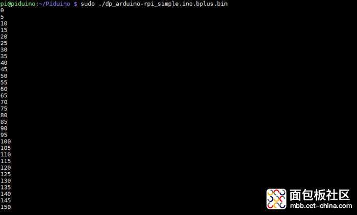
图11 Raspberry Pi控制台输出
高级示例:SPI和I2C
显然,LED闪烁和控制台输出等功能可以完成许多不错的项目,但是我认为,如果添加一些更高级的功能,比如I2C和SPI,我们就可以做更多事情。RasPiArduino框架同样支持这些功能,所以我们可以用I2C总线将不同的传感器连至Raspberry;或者让Raspberry通过SPI总线与各通信模块进行通信。对于I2C器件,我使用的是罗姆传感器评估套件中的BH1745NUC颜色传感器;对于SPI,我用的是SX1278 LoRa模块。这两者的运行电压逻辑都是3.3V,因此只需几根线缆就可以将它们与Raspberry连接起来,非常简单。
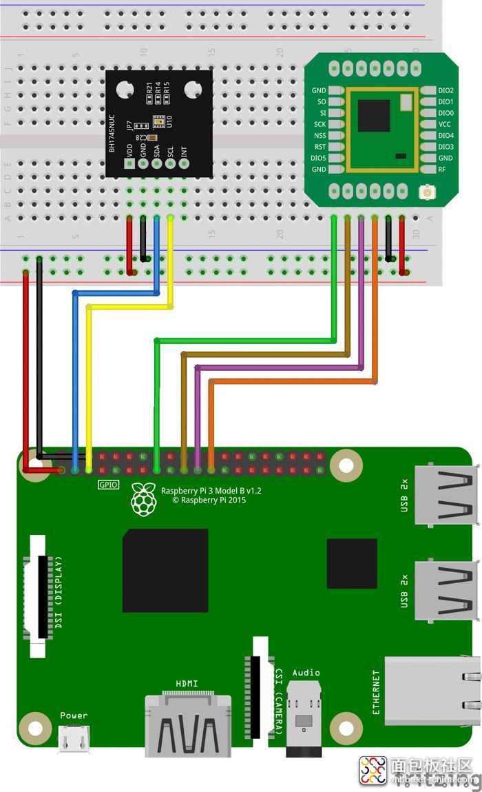
图12 本例的接线示意图
多亏了LoRaLib和RohmMultiSensor库,系统代码也非常简单!基本上就是LoRaLib库中的接收器示例代码加上RohmMultiSensor库中的BH1745NUC示例代码。
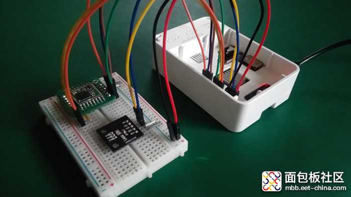
图13 已连接SX1278无线模块和BH1274NUC颜色传感器的Raspberry Pi
在此示例中,所有重要信息都被打印到Raspberry控制台。我们可以看到,SX1278成功接收到了包含字符串“Hello Raspberry!”的数据包(从Arduino通过LoRenz开发板发送),而且颜色传感器测量的值也是正确的!
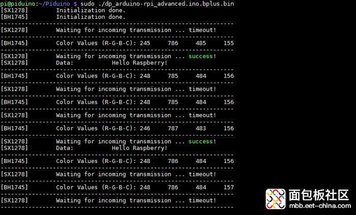
图14 Raspberry Pi控制台输出
结论
那么结论是:我们可以将Raspberry Pi当作Arduino开发板进行编程吗?绝对可以!但是,这两种系统都有优缺点。Raspberry的处理速度更快,Arduino功耗更低;Raspberry具有内置的HDMI和以太网端口,而Arduino具有内置的模数转换器。其他对比不再一一列举。但是,这归根结底是因为Arduino和Raspberry的应用场景不同。比如,如果您需要构建基于电池的传感器监控系统,请选Arduino。如果您需要通过机器学习来处理相机图片,请选Raspberry Pi。总之,我们必须根据系统要处理的任务类型选择适当组件,反之则不行。

Jan Gromes
Jan目前在布尔诺理工大学学习电气工程。他拥有多年使用Arduino和其他微控制器构建项目的经验。他的特殊兴趣在于机器人系统的机械设计。
来源:techclass.rohm


 /5
/5 

