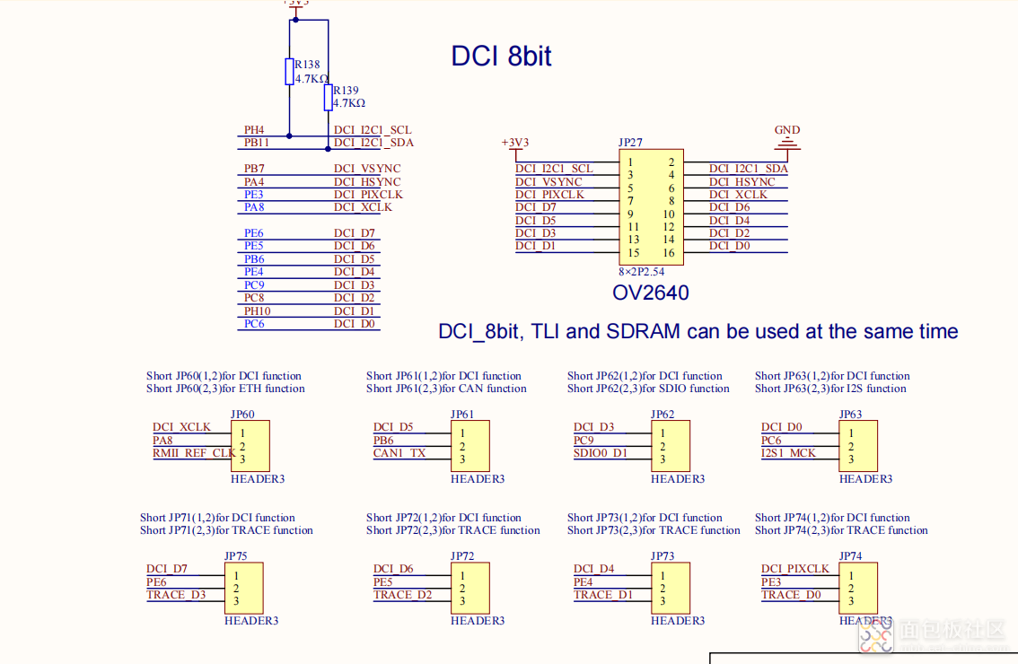
摄像头接口如下:

参考了例程重新整理了一下摄像头驱动。首先初始化GPIO接口,然后就是DCI外设初始化,通过DMA方式将DCI的摄像头数据传到SDRAM地址0XC1000000。
下面是DCI的初始化:
/*!
\brief configure the DCI to interface with the camera module
\param[in] none
\param[out] none
\retval none
*/
void dci_config(void)
{
dci_parameter_struct dci_struct;
dma_single_data_parameter_struct dma_single_struct;
rcu_periph_clock_enable(RCU_GPIOA);
rcu_periph_clock_enable(RCU_GPIOB);
rcu_periph_clock_enable(RCU_GPIOC);
rcu_periph_clock_enable(RCU_GPIOE);
rcu_periph_clock_enable(RCU_GPIOH);
rcu_periph_clock_enable(RCU_GPIOG);
rcu_periph_clock_enable(RCU_DCI);
/* DCI GPIO AF configuration */
/* configure DCI_PIXCLK(PE3), DCI_VSYNC(PB7), DCI_HSYNC(PA4) */
gpio_af_set(GPIOE, GPIO_AF_13, GPIO_PIN_3);
gpio_af_set(GPIOB, GPIO_AF_13, GPIO_PIN_7);
gpio_af_set(GPIOA, GPIO_AF_13, GPIO_PIN_4);
gpio_mode_set(GPIOE, GPIO_MODE_AF, GPIO_PUPD_NONE, GPIO_PIN_3);
gpio_output_options_set(GPIOE, GPIO_OTYPE_PP, GPIO_OSPEED_100_220MHZ, GPIO_PIN_3);
gpio_mode_set(GPIOB, GPIO_MODE_AF, GPIO_PUPD_NONE, GPIO_PIN_7);
gpio_output_options_set(GPIOB, GPIO_OTYPE_PP, GPIO_OSPEED_100_220MHZ, GPIO_PIN_7);
gpio_mode_set(GPIOA, GPIO_MODE_AF, GPIO_PUPD_NONE, GPIO_PIN_4);
gpio_output_options_set(GPIOA, GPIO_OTYPE_PP, GPIO_OSPEED_100_220MHZ, GPIO_PIN_4);
/* configure DCI_D0(PC6), DCI_D1(PH10) DCI_D2(PC8), DCI_D3(PC9), DCI_D4(PE4), DCI_D5(PB6), DCI_D6(PE5), DCI_D7(PE6) */
gpio_af_set(GPIOC, GPIO_AF_13, GPIO_PIN_6);
gpio_af_set(GPIOC, GPIO_AF_13, GPIO_PIN_8);
gpio_af_set(GPIOC, GPIO_AF_13, GPIO_PIN_9);
gpio_af_set(GPIOB, GPIO_AF_13, GPIO_PIN_6);
gpio_af_set(GPIOE, GPIO_AF_13, GPIO_PIN_4);
gpio_af_set(GPIOE, GPIO_AF_13, GPIO_PIN_5);
gpio_af_set(GPIOE, GPIO_AF_13, GPIO_PIN_6);
gpio_af_set(GPIOH, GPIO_AF_13, GPIO_PIN_10);
gpio_mode_set(GPIOH, GPIO_MODE_AF, GPIO_PUPD_NONE, GPIO_PIN_10);
gpio_output_options_set(GPIOH, GPIO_OTYPE_PP, GPIO_OSPEED_100_220MHZ, GPIO_PIN_10);
gpio_mode_set(GPIOC, GPIO_MODE_AF, GPIO_PUPD_NONE, GPIO_PIN_6);
gpio_output_options_set(GPIOC, GPIO_OTYPE_PP, GPIO_OSPEED_100_220MHZ, GPIO_PIN_6);
gpio_mode_set(GPIOC, GPIO_MODE_AF, GPIO_PUPD_NONE, GPIO_PIN_9);
gpio_output_options_set(GPIOC, GPIO_OTYPE_PP, GPIO_OSPEED_100_220MHZ, GPIO_PIN_9);
gpio_mode_set(GPIOC, GPIO_MODE_AF, GPIO_PUPD_NONE, GPIO_PIN_8);
gpio_output_options_set(GPIOC, GPIO_OTYPE_PP, GPIO_OSPEED_100_220MHZ, GPIO_PIN_8);
gpio_mode_set(GPIOB, GPIO_MODE_AF, GPIO_PUPD_NONE, GPIO_PIN_6);
gpio_output_options_set(GPIOB, GPIO_OTYPE_PP, GPIO_OSPEED_100_220MHZ, GPIO_PIN_6);
gpio_mode_set(GPIOE, GPIO_MODE_AF, GPIO_PUPD_NONE, GPIO_PIN_4);
gpio_output_options_set(GPIOE, GPIO_OTYPE_PP, GPIO_OSPEED_100_220MHZ, GPIO_PIN_4);
gpio_mode_set(GPIOE, GPIO_MODE_AF, GPIO_PUPD_NONE, GPIO_PIN_5);
gpio_output_options_set(GPIOE, GPIO_OTYPE_PP, GPIO_OSPEED_100_220MHZ, GPIO_PIN_5);
gpio_mode_set(GPIOE, GPIO_MODE_AF, GPIO_PUPD_NONE, GPIO_PIN_6);
gpio_output_options_set(GPIOE, GPIO_OTYPE_PP, GPIO_OSPEED_100_220MHZ, GPIO_PIN_6);
/* DCI configuration */
dci_struct.capture_mode = DCI_CAPTURE_MODE_CONTINUOUS;
dci_struct.clock_polarity = DCI_CK_POLARITY_RISING;
dci_struct.hsync_polarity = DCI_HSYNC_POLARITY_LOW;
dci_struct.vsync_polarity = DCI_VSYNC_POLARITY_LOW;
dci_struct.frame_rate = DCI_FRAME_RATE_ALL;
dci_struct.interface_format = DCI_INTERFACE_FORMAT_8BITS;
dci_init(&dci_struct);
/* DCI DMA configuration */
rcu_periph_clock_enable(RCU_DMA1);
rcu_periph_clock_enable(RCU_DMAMUX);
dma_single_data_para_struct_init(&dma_single_struct);
dma_deinit(DMA1, DMA_CH7);
dma_single_struct.request = DMA_REQUEST_DCI;
dma_single_struct.periph_addr = (uint32_t)DCI_DATA_ADDRESS;
dma_single_struct.memory0_addr = (uint32_t)0xC1000000;
dma_single_struct.direction = DMA_PERIPH_TO_MEMORY;
dma_single_struct.number = 38400;
dma_single_struct.periph_inc = DMA_PERIPH_INCREASE_DISABLE;
dma_single_struct.memory_inc = DMA_MEMORY_INCREASE_ENABLE;
dma_single_struct.periph_memory_width = DMA_PERIPH_WIDTH_32BIT;
dma_single_struct.circular_mode = DMA_CIRCULAR_MODE_ENABLE;
dma_single_struct.priority = DMA_PRIORITY_HIGH;
dma_single_data_mode_init(DMA1, DMA_CH7, &dma_single_struct);
/* DMA interrupt and channel enable */
dma_interrupt_enable(DMA1, DMA_CH7, DMA_CHXCTL_FTFIE);
dma_channel_enable(DMA1, DMA_CH7);
/* enable DMA1 channel 7 */
nvic_irq_enable(DMA1_Channel7_IRQn, 0U, 1U);
}
复制代码/*!
\brief ckout0 initialization
\param[in] none
\param[out] none
\retval none
*/
void ckout0_init(void)
{
rcu_periph_clock_enable(RCU_GPIOA);
gpio_af_set(GPIOA, GPIO_AF_CKOUT, GPIO_PIN_8);
gpio_mode_set(GPIOA, GPIO_MODE_AF, GPIO_PUPD_PULLUP, GPIO_PIN_8);
gpio_output_options_set(GPIOA, GPIO_OTYPE_PP, GPIO_OSPEED_60MHZ, GPIO_PIN_8);
rcu_ckout0_config(RCU_CKOUT0SRC_HXTAL, RCU_CKOUT0_DIV2);
}
/*!
\brief DCI camera outsize set
\param[in] width: outsize width
\param[in] height: outsize height
\param[out] none
\retval 0x00 or 0xFF
*/
uint8_t ov2640_outsize_set(uint16_t width, uint16_t height)
{
uint16_t outh;
uint16_t outw;
uint8_t temp;
if(width % 4) {
return 0xFF;
}
if(height % 4) {
return 0xFF;
}
outw = width / 4;
outh = height / 4;
dci_byte_write(0xFF, 0x00);
dci_byte_write(0xE0, 0x04);
dci_byte_write(0x5A, outw & 0xFF);
dci_byte_write(0x5B, outh & 0xFF);
temp = (outw >> 8) & 0x03;
temp |= (outh >> 6) & 0x04;
dci_byte_write(0x5C, temp);
dci_byte_write(0xE0, 0x00);
return 0;
}
复制代码整个初始化如下:
/*!
\brief DCI camera initialization
\param[in] none
\param[out] none
\retval 0x00 or 0xFF
*/
uint8_t dci_ov2640_init(void)
{
uint8_t i;
sccb_config();
dci_config();
ckout0_init();
delay_1ms(100);
/* OV2640 reset */
if(dci_byte_write(0xFF, 0x01) != 0) {
return 0xFF;
}
if(dci_byte_write(0x12, 0x80) != 0) {
return 0xFF;
}
delay_1ms(10);
for(i = 0; i < sizeof(ov2640_svga_init_reg_tbl) / 2; i++)
{
if(0 != dci_byte_write(ov2640_svga_init_reg_tbl[i][0], ov2640_svga_init_reg_tbl[i][1]))
{
return 0xFF;
}
}
delay_1ms(100);
for(i = 0; i < (sizeof(ov2640_rgb565_reg_tbl) / 2); i++)
{
if(0 != dci_byte_write(ov2640_rgb565_reg_tbl[i][0], ov2640_rgb565_reg_tbl[i][1]))
{
return 0xFF;
}
}
delay_1ms(100);
ov2640_outsize_set(320, 240);
dci_ov2640_id_read(&ov2640id);
return 0;
}
复制代码DMA中断函数如下:
/*!
\brief this function handles DMA1_Channel7_IRQ interrupt request
\param[in] none
\param[out] none
\retval none
*/
void DMA1_Channel7_IRQHandler(void)
{
if(dma_interrupt_flag_get(DMA1, DMA_CH7, DMA_INT_FLAG_FTF))
{
int i = 0, x = 0, y = 0;
dma_channel_disable(DMA1, DMA_CH7);
dma_interrupt_flag_clear(DMA1, DMA_CH7, DMA_INT_FLAG_FTF);
dma_channel_enable(DMA1, DMA_CH7);
}
}
复制代码
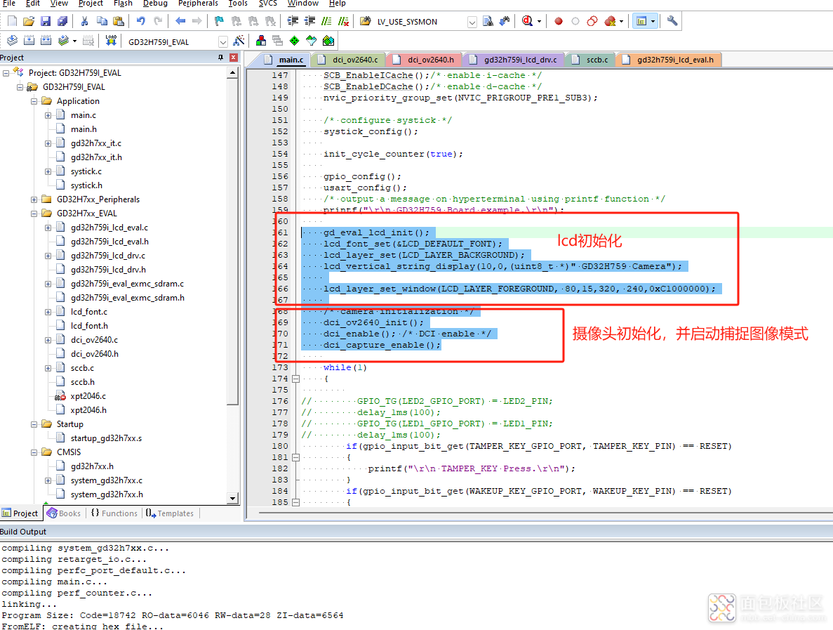
int main(void)
{
/* enable the CPU cache */
SCB_EnableICache();/* enable i-cache */
SCB_EnableDCache();/* enable d-cache */
nvic_priority_group_set(NVIC_PRIGROUP_PRE1_SUB3);
/* configure systick */
systick_config();
init_cycle_counter(true);
gpio_config();
usart_config();
/* output a message on hyperterminal using printf function */
printf("\r\n GD32H759 Board example.\r\n");
gd_eval_lcd_init();
lcd_font_set(&LCD_DEFAULT_FONT);
lcd_layer_set(LCD_LAYER_BACKGROUND);
lcd_vertical_string_display(10,0,(uint8_t *)" GD32H759 Camera");
lcd_layer_set_window(LCD_LAYER_FOREGROUND, 80,15,320, 240,0xC1000000);
/* camera initialization */
dci_ov2640_init();
dci_enable(); /* DCI enable */
dci_capture_enable();
while(1)
{
// GPIO_TG(LED2_GPIO_PORT) = LED2_PIN;
// delay_1ms(100);
// GPIO_TG(LED1_GPIO_PORT) = LED1_PIN;
// delay_1ms(100);
if(gpio_input_bit_get(TAMPER_KEY_GPIO_PORT, TAMPER_KEY_PIN) == RESET)
{
printf("\r\n TAMPER_KEY Press.\r\n");
}
if(gpio_input_bit_get(WAKEUP_KEY_GPIO_PORT, WAKEUP_KEY_PIN) == RESET)
{
printf("\r\n WAKEUP_KEY Press.\r\n");
}
if(gpio_input_bit_get(USER_KEY_GPIO_PORT, USER_KEY_PIN) == RESET)
{
printf("\r\n USER_KEY Press.\r\n");
}
}
}
复制代码这里重新初始化lcd显示的Layer1为摄像头尺寸320*240分辨率。并且显存直接设置成摄像头的数据区地址0xC1000000.
lcd_layer_set_window(LCD_LAYER_FOREGROUND, 80,15,320, 240,0xC1000000);
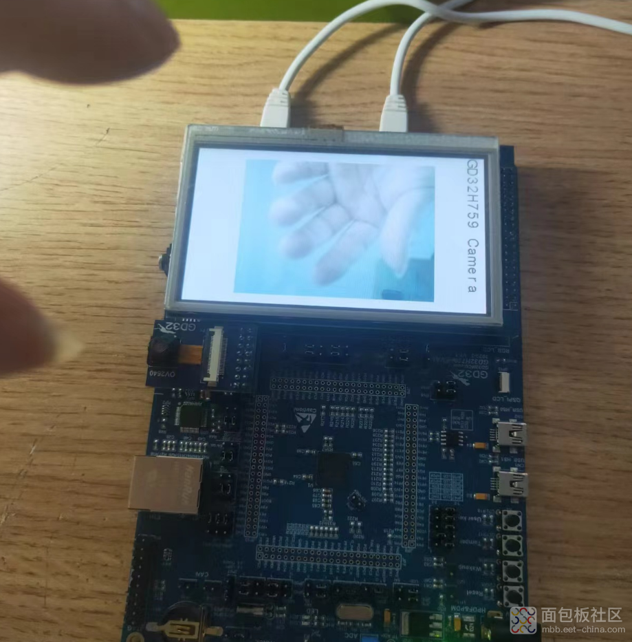
复制代码编译下载之后就可以在lcd上看到摄像头的内容了。

工程:
 GDH7_Demo.zip
(1.22 MB, 下载次数: 9)
热门资料
全部回复 0
 暂无评论,快来抢沙发吧


 /4
/4 

